

9. Measurement Instrumentation
9.1 Temperatures:
9.1.1 Equipment:
9.1.1.1 Temperature measurement equipment and locations for the seven required temperatures are specified. Alternative temperature measurement equipment shall be approved by the TMC. The accuracy and resolution of the temperature measurement sensors and the complete temperature measurement system shall follow the guidelines detailed in ASTM Research Report RR: D02-1218.
9.1.1.2 If thermocouples are used, all thermocouples except the intake-air thermocouple shall be premium, sheathed, grounded types with premium wire. The intake-air thermocouple may be an open-tip type. Thermocouples of 0.125, 0.1875, or 0.25-in. (3.2, 4.8, or 6.4-mm) diameter may be used. However, 0.125-in. (3.2-mm) thermocouples are recommended at locations that require short immersion depths to prevent undesirable temperature gradients. Thermocouples, wires, and extension wires should be matched to perform in accordance with the special limits of error as defined in ANSI MC96.1. Either Type J (iron-constantan) or Type T (copper-constantan) thermocouples are acceptable (see ANSI MC96.1).
9.1.1.3 Resistance thermometer detectors (RTDs) are acceptable alternatives to thermocouples. However, if the TMC is not familiar with the particular RTDs used, the laboratory will be required to demonstrate equivalent system accuracy to the specifications noted in 9.1.1.2 (see ANSI MC96.1).
9.1.2 Engine Coolant Inlet - Install the tip at the center of the flow stream in the perpendicular intersection of the tee fitting located 12 to 16-in. (300 to 410-mm) upstream from the water pump inlet (see Fig. A3.7). The recommended thermocouple diameter is 0.125 in. (3.2 mm).
9.1.3 Engine Coolant Outlet - Install the tip of the thermocouple at the center of the flow stream in the modified thermostat housing. The thermocouple tip shall be within 1 in. (25.4 mm) of the cylinder head. The inside diameter or inner orifice of the thermostat housing shall be no smaller than the Ford factory orifice and no larger than the cylinder head coolant inlet passage.
9.1.4 Engine Oil Inlet - Install the tip at the base of mounting face of the adapter block (see Fig.A3.10 and Fig.A3.13). The recommended thermocouple diameter is 0.125 in. (3.2 mm).
9.1.5 Engine Oil Outlet - Install the tip at the center of the cross fitting attached to the bottom of the heat exchanger (see Fig. A3.10). The recommended thermocouple diameter is 0.125 in. (3.2 mm).
9.1.6 Intake Air - Install the tip midstream in the intake-air horn adapter (see Fig. A3.4). A 0.25-in. (6.4-mm) thermocouple is adequate if an open-tip thermocouple is used.
9.1.7 RAC Coolant Inlet - Install the tip at the center of the cross fitting attached to the RAC inlet fitting (see Fig.A3.14). The recommended thermocouple diameter is 0.125 in. (3.2 mm).
9.1.8 Marine Manifold Coolant - Install the tip at the perpendicular intersection of the tee fitting located on the outlet (upper) port of the marine manifold (see Fig. A3.8). Since the marine manifold coolant temperature is not a controlled parameter, a 0.25-in. (6.4-mm) thermocouple is adequate.
9.1.9 Calibration - Calibrate the engine oil in, engine coolant out, RAC and intake-air temperature measurement sensors every ninety days. Calibrate all other temperature sensors prior to each reference oil test. The temperature measurement system shall indicate within +/- 1°F (0.6°C) of the laboratory calibration standard, which shall be traceable to national standards.
9.2 Pressures:
9.2.1 Equipment - Pressure measurement for each of the eight required parameters is detailed in the following sections. Specific measurement equipment is not specified. This allows reasonable opportunity for adaption of existing test stand instrumentation. However, the accuracy and resolution of the pressure measurement sensors and the complete pressure measurement system shall follow the guidelines detailed in ASTM Research Report RR: D02-1218.
NOTE 8 - Tubing between the pressure tap locations and the final pressure sensors should incorporate condensate traps, as indicated by good engineering practice. This is particularly important in application where low air pressures are transmitted by means of lines that pass through low-lying trenches between the test stand and the instrument console.
9.2.2 Intake Manifold Vacuum - Measure the intake manifold vacuum at the top side of the upper intake manifold as detailed in Fig.A3.21.
9.2.3 Oil Pressure - Make oil pressure measurements at the oil filter adapter housing inlet, oil filter housing outlet, and the rear corner of the cylinder head, as shown in Fig.A3.13. A multi-position selector valve can be utilized to connect the three oil pressure taps to a single pressure sensor. Individually dedicated pressure sensors may also be utilized.
9.2.4 RAC Coolant Pressure - Measure the RAC coolant pressure at the coolant inlet cross fitting, as detailed in Fig.A3.14.
9.2.5 Fuel Pressure - Measure the fuel pressure at the injector rail inlet as shown in Fig.4. When utilizing a pressure gage mounted directly to the injector rail, the gage should be a damped, liquid-filled type.
9.2.6 Intake-Air Pressure - Measure the intake-air pressure at the air horn with the probe, as shown in Fig.1 and detailed in Fig.A3.3, Fig.A3.4, and Fig.A3.5. If a manometer is used, install a liquid trap to prevent manometer fluid from entering the intake-air horn.
9.2.7 Crankcase Pressure - Measure the crankcase pressure at the dipstick tube. The sensor shall be capable of measuring positive and negative pressure. If a manometer is utilized, install a liquid trap to prevent manometer fluid from entering the crankcase.
9.2.8 Exhaust Back Pressure - Measure exhaust back pressure with the exhaust sampling probe downstream of the marine manifold (see Fig.3 and Fig.A3.5). Install the exhaust gas sample and exhaust back pressure probe assembly against the marine manifold. A sensor capable of absolute measurement or a gage measurement corrected with a barometric pressure reading is acceptable. Install a condensate trap between the probe and sensor to accumulate water present in the exhaust gas.
9.2.9 Engine Coolant Pressure - Measure the coolant pressure above the fluid level in the engine reservoir, as shown in Fig.A3.7. Maintain engine coolant system pressure at 10 +/- 1 psig (69 +/- 6.9 kPa).
9.2.10 Calibration - Calibrate all pressure sensors, including the RAC and engine coolant flow differential pressure and coolant pressure measurement sensors prior to each reference oil test. The calibration standard shall be traceable to national standards.
9.3 Flow Rates:
9.3.1 Equipment - Flow rate measurement procedures for each of the four required parameters are detailed in the following subsections. With the exception of the engine coolant and blowby flow rates, measurement equipment is not specified for a given parameter. This allows reasonable opportunity for adaption of existing test stand instrumentation. The accuracy and resolution of the flow rate measurement system shall follow the guidelines detailed in ASTM Research Report RR: D02-1218.
9.3.2 Engine Coolant - Determine the engine coolant flow rate by measuring the differential pressure drop across the specified venturi flowmeter (see Fig.A3.7). The pressure drop is approximately 18 in. (4.5 kPa) H2O in the controlled flow range. Take precautions to prevent air pockets from forming in the lines to the pressure sensor. Transparent lines are beneficial in this application.
9.3.3 RAC Coolant - Measure the total volumetric coolant flow rate through the RAC.
9.3.3.1 Calibration - Calibrate the flowmeters used in the measurement of both the engine coolant flow rate and RAC coolant flow rate before every reference oil test. Calibrate the flowmeters as installed in the system at the test stand. Alternatively, the flowmeters may be detached from the test stand and calibrated, providing the adjacent upstream and downstream plumbing is left intact during the calibration process. Calibrate the flowmeters with a turbine flowmeter or by a volume/time method, at Stage 1 operating conditions.
9.3.4 Blowby:
9.3.4.1 Measure the blowby flow rate using the apparatus shown in Fig.7. The measurement system routes the blowby through an external, sharp-edged orifice and into the engine intake manifold by means of an auxiliary (dummy) PCV valve. Mount the orifice plate with the flow in a horizontal position. Maintain crankcase pressure at 0.0 +/- 0.1 in. (0.0 +/- 25 Pa) during operation of the system to minimize the potential for crankcase leakage. Mount the dummy PCV valve in a vertical position.
9.3.4.2 Determine the blowby flow rate by measuring the differential pressure drop across the sharp-edged orifice; an inclined manometer or differential pressure sensor is required for measurement of the differential pressure drop. The crankcase pressure sensor shall have a range from 0 to 4 in. (0 to 1 kPa) H2O and be adequately damped to indicate a zero gage pressure.
9.3.4.3 The sharp-edged orifice assembly is specifically designed for blowby flow rate measurement and shall be fabricated in strict compliance with the specifications, that are available from the TMC. The assembly contains five orifices. The 0.375-in. (9.53-mm) orifice is generally satisfactory for the range of blowby flow rate encountered. The complete orifice assembly can also be purchased from the supplier listed in Appendix X2. Additional details concerning fabrication of the flow rate measurement orifice assembly and measurement of blowby flow rate can be found in Footnote 14.
9.3.4.4 Maintenance - Clean the blowby measurement apparatus at least once every seven days. Replace the O-ring with each cleaning. Exercise particular care when cleaning the orifice meter assembly. Clean the three-way valve by soaking the valve in agitated organic solvent (see 7.7.3) until clean, followed by hot [>140°F (>60°C)] water rinse and spray rinse with aliphatic naphtha. Use compressed air to force air-drying. Inspect the port passages and remove any carbonaceous deposits by scraping. If the valve is disassembled for cleaning, make sure the core is properly seated upon reassembly. (Warning—Internal leakage within the three-way valve may cause some of the blowby gas to pass directly to the intake manifold from the test PCV valve and result in erroneous blowby flow rate measurements (see Fig.7)).
9.3.4.5 Calibration - Calibrate the blowby orifice meters used for laboratory measurements every six months. Calibrate laboratory blowby measurements standards, used for the calibration of other meters, yearly. The calibration standard shall be traceable to national standards. Calibrate the temperature measuring devices in the blowby system every six months.
9.4 Fuel Consumption - Determine the fuel consumption rate by measuring the amount of make-up fuel flowing from the external fuel tank. The measurement point is upstream of the return flow from the fuel rail (see Fig.4).
9.4.1 Calibration - Calibrate mass flow systems or gravimetric systems before every reference oil test. Volumetric systems shall be temperature-compensated and calibrated against a mass flow device. Values obtained with the test stand measuring device shall be within 1 % of the calibration standard values.
9.5 Speed and Load:
9.5.1 Required Capabilities - The dynamometer speed and load control systems shall be capable of maintaining the limits specified in Table 2 and meet the ramping requirements specified in Table 4 and Table 5. These limits require control within +/- 0.4 % for operation during Stages 1 and 2. Because the dynamometer and driveline frictional losses may approach the Stage 3 load, manage the control input and system response during Stage 3 carefully to maintain engine operation within the specified tolerances. These tolerances are necessary to maintain a stable air-fuel ratio during Stage 3. Hydraulic dynamometers have a high residual load and may not be suitable for operation during Stage 3.
9.5.2 Suitable Systems - Both partial and full closed-loop systems have been successfully utilized. A typical partial closed-loop system maintains speed by varying dynamometer excitation and maintains load by a fixed throttle. A typical closed-loop system maintains engine speed by varying dynamometer load and maintains engine load by varying the engine throttle position.
9.5.3 Calibration - Calibrate the load measurement and readout system with deadweights at least once per test. Calibration of the zero scale readout is recommended once per day when the test stand is in use. Calibrate the speed measurement system prior to each reference oil test.
9.6 Exhaust Gas:
9.6.1 Equipment:
9.6.1.1 Precision instruments for measurement of O2, CO, and NOx are required. Equipment suitable for automobile emission measurements is recommended. Precision nondispersive infrared instrumentation for CO and polarographic instrumentation for O2 are suggested (see SAE J254). Response time is an important consideration in the performance of this instrumentation. A CO meter capable of measuring CO from 0 to 20 % is also required, for determining CO values during Stage 2 to 3 and 3 to 1 transitions. An extended range air-fuel ratio (UGEO) sensor can also be used to determine CO values during transitions. To decrease the response time of the meter, it is recommended that the CO meter or UGEO sensor be mounted as close to the stand as possible or in a portable installation.
9.6.1.2 A typical exhaust gas analysis system is shown in Fig.3. The required instrument calibration gases are listed in Note of Fig.A3.6, and system design details are specified in Fig.A3.5 and Fig.A3.6. (Warning - Safety precautions are necessary concerning venting carbon monoxide, nitrous oxide, and ozone gases from the analyzer instruments.) (Warning - Long sample lines and unnecessary fitting connections or valves between the sample probe and the analyzer increase the potential for measurement error.)
9.6.2 Calibration - General - Calibrate the exhaust gas analysis equipment before each set of measurements taken during the test. The calibration technique should compensate for the flow rate sensitivity of the exhaust gas analysis meters.
9.6.3 CO Meter Calibration for Transitions - For ramping transitions, calibrate the CO meter from 0 to 15 % CO, as well as response time to ensure accurate readings during stage transitions. A zero and span calibration is required every day that the CO meter is used. No more than seven stage transition recordings or a maximum of one week is to transpire between a full stabilized and response calibration.
9.6.3.1 Conduct stabilized calibrations with the following nominal calibration gases: 0, 0.5, 6.5, and 15 % CO. The same trace recorder used for the transition traces (see Fig.A7.18) is used for the calibration. Zero and span the CO meter to the 15 % CO bottle. The calibration of the indicated and actual CO measurements of 0.5, 6.5, and 15 % CO shall be within 0.5 % and the zero and span within 0.2 % CO.
9.6.3.2 Conduct response calibrations with the 0.5 and 15 % nominal CO calibration gases. Use a solenoid valve to switch between the calibration sample bottles (see Fig.A7.19). Connect the solenoid valve directly to the longest sample line in the CO measurement system. Make the connection where the sample line would normally go onto the exhaust pipe. Use the same sample flow rate for the calibration as that used for transition trace recordings. The same trace recorder used for the transition trace recordings (see Fig.A7.18) is used for calibration. Show the solenoid switching voltage on one of the trace recorder channels. The solenoid valve switches the sample gas from the 0.5 to 15.0 to 0.5 % CO bottles at 40-s intervals. For satisfactory calibration, the indicated CO % shall duplicate the actual 15 % CO bottle value +/- 0.3 % CO (see Fig.A7.18).
9.6.3.3 If an UEGO sensor is used to determine CO values, correlate the sensor voltage output every six months or after 1000 h of use, whichever occurs first, to CO levels at the following conditions:
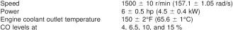
Install the UEGO sensor to avoid obstruction of the exhaust backpressure and air-fuel ratio probes. Where continuous air purge is maintained on the air-fuel ratio probe, install the sensor upstream of the exhaust backpressure and air fuel ratio probes.
9.7 Humidity - Measure humidity with the laboratory's primary humidity stream. Correct each reading for non-standard barometric conditions, using the following equation:
Humidity (corrected) = 4354 x (Psat/(Pbar - Psat))
where:
Psat = saturation pressure, in. Hg, and
Pbar = barometric pressure, in. Hg.
Metric Units:
Humidity (corrected) = 621.98 x (Psat/Pbar - Psat))
where:
Psat = saturation pressure, mm Hg, and
Pbar = barometric pressure, mm Hg.
9.7.1 Calibration - Calibrate the primary laboratory measurment system at each stand on a semiannual basis using a hygrometer with a minimum dew point accuracy of +/- 1°F at 60°F (+/- 0.55° C at 16°C). Locate the sample tap on the air supply line to the engine, between the main duct and 2 ft upstream of the intake air horn. The calibration consists of a series of paired humidity measurments comparing the laboratory system with the calibration hygrometer. The comparison period lasts from 20 min to 2 h with measurements taken at 1 to 6 min intervals, for a total of 20 paired measurements. The measurement interval shall be appropriate for the time constant of the humidity measuring instruments.
9.7.1.1 Verify that the flow rate is within the equipment manufacturer's specification, and that the sample lines are non-hygroscopic. Correct dew point hygrometer measurements to standard conditions (29.92 in. Hg [101.12 kPa]) using the appropriate equation (see 9.7). Compute the difference between each pair of readings and calculate the mean and standard deviation of the 20 paired readings, using equations Eq A13.1 and Eq A13.2 in Annex A13. The absolute value of the mean difference shall not exceed 10 grains/lb (1.43 g/kg) and the standard deviation shall not be greater than 5 grains/lb (0.714 g/kg). If these conditions are not met, investigate the cause, make repairs, and recalibrate. Maintain calibration records for two years.