

8. Preparation of Apparatus
8.1 This section assumes that the engine test stand facilities and hardware as described in Section 6 are in place. Emphasis is on the recurring preparations needed in the routine conduct of the test.
8.2 Test Stand Preparation:
8.2.1 Instrument Preparation - Calibrate, and record for future reference, the temperature measuring system in a manner consistent with good laboratory practices.
8.2.2 Hose Replacement - Inspect all hoses and replace any that have deteriorated. Check for internal wall separations that would cause flow restriction.
8.3 Engine Preparation:
8.3.1 General Assembly Instructions - Assemble the external engine accessory components according to the detailed description in the International T 444E Diesel Engine Service Manual. In cases of disparity, however, the explicit instructions contained in this test method take precedence over the service manual.
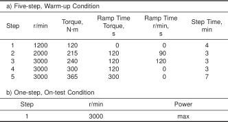
NOTE - The test sequence consists of a five-step, warm-up condition followed by a one-step, on-test condition.
8.3.1.1 Do not use sealers in tape form.
NOTE 3 - Loose shreds of tape can circulate in the engine oil and plug critical orifices.
8.3.2 Bolt Torque Specifications - When installing the engine components, use a calibrated torque wrench to obtain the values specified in the International Engine Service Manual.
NOTE 4 - Over-torquing can damage threads, thereby preventing attainment of the correct torque, and may require replacement of the damaged part.
NOTE 5 - The specified torque values apply only to clean and lightly-lubricated threads. Dirty or dry threads produce friction that prevents accurate measurement of the torque.
8.3.3 Sealing Compounds - Use only International approved room temperature vulcanized (RTV) silicone rubber (T442) sealers. Passivate new sealants by running the engine under one-step, on-test conditions (see Table 3b) for 20 h, using an engine as detailed in 7.1.
NOTE 6 - Silicone from new silicone-based seals may contaminate the used oil thereby contributing to aeration. Passivation removes this silicone.
8.3.4 Thermostat - Modify the thermostat on the test engine so that it remains open.
8.3.5 Alternator - If an alternator is installed on the engine, do not energize the fields to maintain battery charge because the resulting absorption of power from the engine can adversely affect the test result.
9. Calibration
9.1 Test Stand/Engine Calibration:
9.1.1 Procure a supply of reference oils, as needed (see 9.1.2), from the TMC.
9.1.1.1 These oils have been formulated or selected to represent specific chemistry types, or performance levels, or both. Each reference oil is identified by a unique identifying code on the container label.
9.1.2 Test the Reference Oils:
9.1.2.1 Reference oil tests on each test stand/engine shall be conducted according to ASTM TMC Lubricant Test Monitoring System (LTMS) guidelines. Calibration tests using the reference oils are required after 30 operationally valid, non-reference oil test runs or one year, whichever is sooner. If TMC-acceptable results are obtained on the reference oils, the test stand/engine is considered calibrated.
9.1.2.2 The effective date of a reference oil test is the LTMS date and time of the reference test. Test start time is defined as the introduction of the reference oil into the engine. The LTMS date and time are defined as the date and time the test was completed unless a different date and time are assigned by the TMC.
9.1.3 Immediately after completion of the test analysis, report the reference oil test results to the TMC according to the following guidelines:
9.1.3.1 Use the appropriate data reporting forms (see 12.1 and Note 13) and complete all the required blank fields.
9.1.3.2 Transmit the reference oil test data by electronic means or by facsimile, including all the reporting forms in the transmission.
NOTE 7 - Specific protocols for the electronic transmission of test data are available from the TMC.
9.1.3.3 In addition to the previously transmitted data, send by mail or other courier, one copy of the final reference oil test report to the TMC. This report shall be received within 30 days of test completion. The signatory line on this report cover sheet requires an original signature by an authorized representative of the testing laboratory.
9.1.4 The TMC will review the transmitted reference oil test results and use the LTMS to determine test acceptability.
9.1.5 Reference Oils Identification - Do not subject reference oils to either physical or chemical analyses for identification purposes. Identifying the oils by analyses could undermine the confidentiality required to operate an effective blind reference system. Therefore reference oils are supplied with the explicit understanding that they will not be subjected to analyses other than those specified within this procedure unless specifically authorized by the TMC. In such instances, supply written confirmation of the circumstances involved, the data to be obtained, and the name of the person requesting the analysis to the TMC.
NOTE 8 - Policies for the use and analysis of ASTM reference oils are available from the TMC.
9.2 Instrument Calibration - Record all instrument calibrations for further reference. For a new engine, perform a complete test stand instrument calibration prior to conducting the initial reference test. For a previously calibrated (existing) stand/engine, calibrate the following systems prior to the next reference test: (1) engine load measurement; (2) fuel flow, and (3) engine speed measurement. As a minimum, calibrate all other instruments after 30 non-reference oil tests or every year, whichever is sooner.
9.2.1 Thermocouples and Temperature Measurement System - Use Type E thermocouples as the minimum quality temperature measuring system. Prior to running a new engine reference, or as needed, check the calibration of the test stand temperature measurement system (thermocouple through to the readout) at the test stand using the existing readout system. For those temperatures controlled during test operation (see Table 4a), individual temperature sensors shall indicate within +/- 0.56°C of the laboratory calibration standards.