

11. Engine Operating Procedure
11.1 Dipstick and Hole Plug - Remove the calibrated dipstick and close off the dipstick hole in the block with the required plug, for all engine operation. See the Sequence IIIG Engine Assembly Manual, Section 1 Sheet 2.
11.2 Dipstick Hole O-ring - Periodically replace the O-ring on the dipstick hole plug, part number 2-106, to ensure a good seal between the plug and the engine block.
11.3 Engine Start-up and Shutdown Procedures - Start and stop Sequence IIIG engines according to the following procedures and the test states and set points listed in Annex A10.
11.4 Start-up - Use the following procedure in starting Sequence IIIG engines:
11.4.1 Before cranking engine, supply 13 V to 15 V dc power to the Powertrain Control Module, fuel pump, and all AFR control units for a minimum of 30 s to assure all systems are prepared for closed loop AFR control. The lambda sensors are pre-heated and ready for closed-loop control when the AFR readings are over 20:1 prior to engine start.
11.4.2 Simultaneously, start the coolant flowing through the exhaust manifolds.
11.4.3 If the engine fails to start after 5 s, determine the problem and take corrective action taken before any further attempts are made. Make a log entry of any failed attempt and any corrective action in the test report.
11.4.4 After starting the engine, verify that oil pressure is adequate, and the speed is set to 1500 r/min and the power to 6.34 kW.
11.5 Scheduled Shutdown - Use the following procedure in stopping Sequence IIIG engines:
11.5.1 Reduce the engine speed and load to 1500 r/min and 6.34 kW with a linear ramp-down over 30 s (if applicable). Within 90 s, remove the required oil purge sample and analysis sample of 472 mL (see 11.7) from the engine oil sampling valve and adjust all temperatures for engine shutdown.
11.5.1.1 Prior to shutdown on the initial run and at the end of test, add the 472 mL purge back to the engine.
11.5.1.2 Prior to shutdown on all oil levels except the initial and the end of test, add the 472 mL of new oil, plus an additional 59 mL of new oil to the engine prior to shutdown.
11.5.2 Turn off power to the Powertrain Control Module (PCM).
11.5.3 With the engine stopped, stop the coolant flow through the exhaust manifolds and continue with the oil sampling and leveling procedure (see 11.7 through 11.8.7).
11.6 Non-Scheduled Shutdowns - For any non-scheduled shutdowns, record in detail the time off test, the reasons for the shutdown and any other pertinent observations. Include this record in the test note Section of the final test report.
11.7 Oil Sampling - With the engine running at 1500 r/min, remove all oil samples from the engine oil sampling valve according to the following instructions:
11.7.1 Before taking the samples in each of the following steps, first remove a purge or leveling sample of 472 mL; then remove the oil sample of the specified volume.
11.7.2 Take an analysis sample of 236 mL at the end of the initial run (identified as the initial sample) and at the end of the 100 h test.
11.7.3 Take a 59 mL sample at the end of every 20 h during the test, except at the end of the 100 th hour when taking an end-of-test sample of 236 mL.
11.8 Oil Leveling - Determine the oil level in the crankcase according to the following instructions:
11.8.1 Determine the oil level after the initial run of 10 min and after each 20 h of test.
11.8.2 Stop the engine according to the procedure in 11.5 for 15 min to allow the oil to return to the crankcase.
11.8.3 During the oil-leveling period of 20 min, maintain the condenser temperature at 40 °C and the engine coolant temperature at 49 °C.
11.8.4 Determine the oil level after the 15 min period, in millimetres, using the calibrated dipstick (see Annex A6).
11.8.5 Following the initial run, record the oil level on Fig.A12.1, according to 11.8.6. Use this level as the full mark for the test. Enter zero millilitres as the computed oil level on Fig.A12.1.
11.8.6 After each 20 h of the 100 h test, except at the end of test, add 59 mL of new oil to replace the sample taken; also add 472 mL of new oil to the engine.
11.8.7 After each 20 h of the 100 h test, except at the end of test, add oil to the crankcase from the leveling sample of 472 mL to bring the oil level, as nearly as possible, back to that following the initial run. At the end of test, return the entire 472 mL purge sample to the engine. Discard any excess leveling sample. Record the results on Fig.A12.1.
11.9 Air-to-Fuel Ratio Measurement and Control - Measure the air-to-fuel ratio using the lambda sensors throughout the test. Control the air-to-fuel ratio using the lambda sensor output as feedback for the Powertrain Control Module. See Annex A9.
11.10 Air-to-Fuel Ratio Verification - Air-to-fuel ratio measurements made by the lambda sensors may be verified using exhaust gas analysis or real-time feedback systems, or both. Calibrate real time sensors per the manufacturer's recommendation at least every 6 months. If a real time system allows for percent O2 compensation, perform the calculation. When using gas analysis, verify according to the following:
11.10.1 By means of exhaust gas analysis, measure the volume percent of CO2, CO, and O2 using an electronic gas analyzer.
11.10.2 Enter either Fig.A9.1 or TableA 9.1, constructed for the Sequence IIIG fuel, with the CO2, CO, and O2 values to determine the air-to-fuel ratio.
11.10.3 For air-to-fuel ratios greater than 15:1 (lean), when the analysis shows a CO concentration in the exhaust gas, correct the analysis as follows:
11.10.3.1 Determine the corrected O2 using this relationship:
Corrected O2 = Observed % O2 - 0.5 (observed % CO)
11.10.3.2 Determine the corrected CO2 using this relationship:
Corrected CO2 = Observed % CO2 + observed % CO
11.10.3.3 In either Fig. A9.1 or Table A9.1, enter the corrected O2 and CO2 values to determine the air-to-fuel ratios for the two gases, that shall agree within 0.5 air-to-fuel ratio.
11.10.4 Measure the air-to-fuel ratio using exhaust gas analysis during the first hour of the test to ensure that the lambda sensors are functioning properly.
11.10.5 Measure the air-to-fuel ratio using exhaust gas analysis during test hours 19, 49, and 99 of the test to ensure that the lambda sensors are functioning properly.
11.11 Blowby Flow Rate Measurement - Measure the engine blowby flow rate according to the following instructions, and within 15 min of the end of test, at hours: 1, 6, 11, 16, 21, 26, 31, 36, 41, 46, 51, 56, 61, 66, 71, 76, 81, 86, 91, 96 and 99.
11.11.1 Observe the following requirements:
11.11.2 Measure the blowby flow rate at the condenser outlet.
11.11.3 Seal the dipstick hole during engine operation by using the dipstick-hole plug.
11.11.4 Orient the blowby meter horizontally during measurements.
11.11.5 Direct the blowby gas into a suitable vent hood at all times, other than when the blowby flow rate is being measured. Do not allow the vent system to create a draw on the crankcase.
11.11.6 Connect a surge tank, drawing RX-117431C, to the condenser.
11.11.7 Connect the blowby flow-rate meter to the surge tank.
11.11.8 When permanently installed blowby meters are not used, portable cart applications are allowed. However, position the cart near the testing area for a sufficient time-period to assure temperature stabilization of the system components prior to taking any blowby measurements.
NOTE 10 - Temperature stabilization is necessary to reduce condensation precipitation of the blowby gases. The moisture content of blowby gases is generally between (17 and 20) g/g. Correction factors are based on this and other average gas-analysis data of the blowby gases. Therefore, it is important that the blowby gases being measured at the orifice plate be as close in molecular composition and temperature as possible to the blowby gases exiting the condenser.
11.11.9 Do not evacuate or direct the exhaust line for the engine blowby gas being measured toward any low pressure evacuation systems.
11.11.10 Select an orifice size such that the observed blowby flow, ΔP, lies in the midrange of the calibration curve. Record the orifice size used.
11.11.11 Control the crankcase pressure at 0 Pa +/- 12.4 Pa.
11.11.12 Maintain blowby gas flow through the orifice meter for 2 min or more to ensure flow stability, prior to taking the actual readings. Due to the relatively low flow rates, allow time for the engine blowby gas to fill the system and further enhance temperature stabilization.
11.11.13 Record the uncorrected blowby flow rate in litres per minute and correct it for an atmospheric pressure of 100 kPa and a temperature of 37.8 °C, using the correction factors given in Table A13.1.
11.11.14 Alternatively, use the following equation, on which Table A10.1 is based, to correct the blowby flow rate:
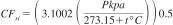
where:
CFsi = corrected blowby flow rate, L/min,
Pkpa = blowby pressure, kPa, and
t°C = temperature, °C.
11.11.15 Disconnect the surge tank from the condenser.
11.12 NOx Determinations - The measurement of NOx is not required. If desired, measure NOx concentrations using suitable exhaust gas analysis equipment at 19 h, 49 h, and 99 h, and record the data in the report form set.
11.13 Data Recording - Record data for all parameters listed in Fig.A10.1 at a minimum of every 2 min.
11.14 Initial Run (10 min) - After charging with the test oil and priming the engine, conduct the 10 min initial run.
11.14.1 Start the engine (see 11.4). Begin timing the 10 min initial run.
11.14.2 Maintain the ignition voltage between 13 V to 15 V.
11.14.3 Make certain that coolant is flowing through the water-cooled exhaust manifolds.
11.14.4 Control the coolant jacket at 50.0 °C +/- 2.0 °C, and the condenser coolant temperature at 40.0 °C +/- 2.0 °C during the initial run. Run the temperature control valve for the oil cooler wide open to obtain maximum cooling during the initial run.
11.14.5 Operate the engine at 1500 r/min, 6.34 kW for 10 min; check for leaks.
11.14.6 Ten minutes after the start of the initial run, and just prior to stopping the engine, remove a purge sample of 472 mL, then take the initial oil sample of 236 mL.
11.14.7 Stop the engine (see 11.5).
11.14.8 Follow 11.7 and 11.8 to determine the oil level after drain-down, in mm; record the value on Fig.A12.1. Use this level as the full mark for the test.
11.15 Engine Oil Quality Testing (100 h) - After completing all phases of the initial run, conduct the engine oil quality evaluation portion of the test for 100 h, according to the following procedure:
11.15.1 Start the engine (see 11.4).
11.15.2 Ensure the throttle body humidified air inlet supply to the engine is connected.
11.15.3 Maintain the ignition voltage between 13 V to 15 V.
11.15.4 Operate the engine under the test conditions listed in Annex A10.
11.15.5 For each 20 h segment of the engine oil quality testing period of 100 h, test time is counted from the moment when all the test conditions listed in Annex A10 are reached and stabilized. Start calculating QI values when temperatures are stable or when test state warm up times are exceeded. See Annex A10. If engine is shut down for any reason except oil leveling, start counting down time. Maximum allowable down time for the IIIG test is 24 h.
11.15.6 Every 20 h, conduct the oil sampling and oil leveling according to 11.5 and 11.6. See Fig.A12.1. Record the time when the final leveling is completed at 100 h; be aware that completion of most of the engine disassembly takes place within 12 h of this time. See 12.2.1.
11.16 Test Termination - Terminate the test as follows:
11.16.1 Terminate the test at the completion of the engine oil quality testing period of 100 h, following the taking of the purge and analysis samples and completion of the end of test oil leveling procedure. Record the end-of-test time after the final, engine oil level procedure.
11.16.1.1 Drain the oil sump.
11.16.1.2 Drain the condenser cooling system.
11.16.1.3 Drain the engine coolant.
11.16.1.4 Remove the engine from the test stand, and transport it to the engine disassembly area for determination of test results.