8. Minimum Detectability
8.1 Minimum detectability is the mass flow rate of the test substance in the carrier gas that gives a detector signal equal to twice the noise level and is calculated from the measured sensitivity and noise level values as follows:
D = 2N/S
where:
D = minimum detectability, g/s,
N = noise level, A, and
S = sensitivity of the detector, A•s/g.
8.2 Test Conditions - Measure sensitivity in accordance with the specifications given in Section 6. Measure noise level in accordance with the specifications given in Section 5. Both measurements must be carried out at the same conditions (for example, carrier gas flow rate and detector temperature) and preferably at the same time. When giving minimum detectability, state the noise level on which the calculation was based.
9. Linear Range
9.1 The linear range of an FID is the range of mass flow rates of the test substance in the carrier gas, over which the sensitivity of the detector is constant to within 5 % as determined from the linearity plot specified in 9.2.2.
9.1.1 The linear range may be expressed in three different ways:
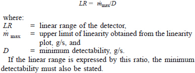
9.1.1.1 As the ratio of the upper limit of linearity, obtained from the linearity plot to the minimum detectability, both measured for the same test substances as follows:

9.1.1.2 By giving the minimum detectability and the upper limit of linearity (for example, from 1 x 10(-12) g/s to 1 x 10(-5) g/s).
9.1.1.3 By giving the linearity plot itself, with the minimum detectability indicated on the plot.
9.2 Method of Measurement:
9.2.1 For the determination of the linear range of an FID, use either the exponential decay or the dynamic methods described in 6.4 and 6.6 respectively. The permeation device method (6.5) will not be suitable because of the limited range of concentrations obtainable with that method.
9.2.2 Measure the sensitivity at various mass flow rates of the test substance in the carrier gas in accordance with the methods described above. Plot the sensitivity versus log mass flow rate on a semilog paper as shown in Fig. 2. Draw a smooth line through the data points. The upper limit of linearity is given by the intersection of this line with a value 0.95 x S, where S is the constant value of sensitivity as determined by a least squares fit of the lower four decades of sample mass flow rate.
9.2.3 In giving the linear range or the linearity plot, specify the test condition in accordance with 7.2.4.

