

12 Measurement of dissipation factor (tan δ)
12.1 Test voltage
The a.c. voltage shall be such as to subject the liquid to an electrical stress between 0.03 kV/mm and 1 kV/mm. The voltage shall be sinusoidal at a frequency between 40 Hz and 62 Hz.
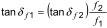
NOTE Generally, within the above frequency range, conversion of results from one frequency to another can be made using the formula:
12.2 Measurement
Where cells are not automatically heated, carry out the dissipation factor measurement within 10 min of reaching a temperature within +/-1 °C of the required test temperature. Apply voltage only during the measurement. On completing the initial measurements (including permittivity and resistivity if required), drain the cell. Refill with a second specimen of the sample following the same procedure and exercising the same precautions used in making the first filling, but omitting rinsing. Repeat the measurement. The two values of tan δ should not differ from each other by more than 0.0001 plus 25 % of the higher of the two values.
NOTE Requirement for a repeat measurement should be qualified for only low values of tan δ. Routine tests do not need to repeat measurements.
If this requirement is not met, continue with further fillings until two consecutive values for tan δ are obtained which agree to within 0.0001 plus 25 % of the higher value of the two values being compared. These shall be accepted as valid measurements.
12.3 Report
Report the dissipation factor (tan δ) of the sample as the mean of the two valid measurements.
The report shall also include:
a) the electrical stress;
b) the frequency of applied voltage;
c) the temperature of test.
13 Measurement of relative permittivity
13.1 Measurement
Measure the capacitance of the clean test cell, first with dry air as the dielectric and then after filling with a liquid of known relative permittivity εn. Calculate the "electrode constant" Ce and the correction capacitance Cg from:

where
Cn is the capacitance of the cell filled with the calibration liquid having the relative permittivity εn;
Ca is the capacitance of the cell with air as the dielectric.
Measure the capacitance Cx of the cell filled with the liquid under test and calculate the relative permittivity εx from

Repeat the test until two consecutive measurements differ by no more than 5 % of the higher value. These shall be accepted as the valid measurement.
NOTE 1 Maximum accuracy is obtained if values Ca, Cn and εn are known at the temperature for which the value Cx is determined.
NOTE 2 When well designed, previously checked three-terminal cells are used or where lower accuracy is acceptable, the term Cg may be neglected, and the relative permittivity may be calculated from the simplified formula:

13.2 Report
Report the relative permittivity of the sample as the mean of the valid measurements.
The report shall also include:
a) the type of cell used and its capacitance with air as the dielectric;
b) the electrical stress;
c) the frequency of applied voltage;
d) the temperature of test.
14 Measurement of d.c. resistivity
14.1 Test voltage
The d.c. test voltage shall be such as to subject the liquid to an electrical stress of 250 V/mm unless otherwise specified.
14.2 Time of electrification
The conventional arbitrary time of electrification is (60 +/- 2) s. Variation in the time of electrification can result in appreciable variation in the test results.
14.3 Measurement
If the dissipation factor has been measured on the test specimen, the electrodes should be short-circuited for 60 s, and resistivity measurement started immediately afterwards.
If only resistivity is to be measured, start the determination as quickly as possible, and not more than 10 min after achieving a temperature within +/-1 °C of the required test temperature.
Establish electrical connections to the measuring apparatus and to the voltage supply so that the inner electrode of the cell is connected to earth. Apply d.c. voltage to the outer electrode and, at the end of the electrification time, record the current and voltage readings.
NOTE 1 Alternatively, instruments reading resistance may be used, provided the other requirements (for example, a stress of 250 V/mm) are complied with.
Short-circuit the cell electrodes for a period of 5 min.
Discard the liquid in the cell, pour in a second specimen from the sample and repeat the measurements.
Calculate the resistivity in ohmmetres by means of:

where
U is the reading of the test voltage, in volts;
I is the reading of the current, in amperes;
K is the cell constant, in metres.
The cell constant K is calculated from the capacitance according to:
K(m) = 0.113 x capacitance (pF) of the empty cell
NOTE 2 0.113 is 10(-12) times the reciprocal of the permittivity of free space.
Direct reading apparatus that performs the calculation automatically may be used.
The measurements on two consecutive fillings shall not differ from each other by more than 35 % of the highest of the values. If this requirement is not met, continue with further fillings until values of resistivity from consecutive samples agree to within 35 % of the highest values.
These shall be accepted as valid measurements.
NOTE 3 A second measurement on each filling, made with the polarity of the applied voltage reversed, may provide information on the cleanliness of the cell and other phenomena. In order to avoid erroneous results, care is necessary with certain electronic instruments that do not have a switch for such reversal.
14.4 Report
Report resistivity of the sample as the mean of the valid measurements.
The report should also include:
a) the electrical stress;
b) the time of electrification;
c) the temperature of test.