

ASTM D3233 Standard Test Methods for Measurement of Extreme Pressure Properties of Fluid Lubricants (Falex Pin and Vee Block Methods)
8. Preparation of Apparatus
8.1 Cleaning:
8.1.1 Thoroughly clean the V-blocks, test journals, lubricant cup, and supports for V-blocks and test journals by washing, successively, with solvent selected in 7.4. Dry the V-blocks, test journals, lubricant cup, and supports by allowing the final solvent to evaporate in air.
8.1.2 After cleaning, handle the test pieces with care to prevent contamination. Particularly, avoid contact of fingers with mating surfaces of V-blocks and test journals.
8.2 Assembly:
8.2.1 Insert the test journal into the test shaft and secure with a new brass locking pin, as shown in Fig. 1 and Fig. 3.
8.2.2 Insert the V-blocks into the recesses of the loading device and swing the V-blocks inward to contact the journal so that the V-grooves are aligned with the journal major axis, as shown in Fig. 1 and Fig. 3.
8.2.3 Place 60 mL of test lubricant in the lubricant cup and raise the cup so that the V-blocks are immersed in the test lubricant. With highly viscous lfuids, open the jaws slightly to ensure that the wear surfaces are covered with the lubricant.
8.2.4 Place the automatic loading device, with attached gage, on the jaw arms.
9. Preparation of True Load Calibration Curve
9.1 On log-log paper (K & E 467080 or equivalent) draw a straight-line plot of load, pounds-force (newtons) (ordinate), versus indentation diameter, millimetres (abscissa) using the data points shown below. Label this curve "True Load" (Note 5).
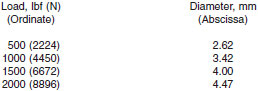
NOTE 5 - Fig. 3 shows the true-load calibration curve for the prescribed 4500-lbf (20 000-N) gage, prepared as covered in 9.1. Copies of Fig. 4, 8 by 11 in., are available at a nominal cost from ASTM. Although not originally used in development of these test methods, the 3000-lb direct reading load gage should be satisfactory providing results are corrected and reported with respect to the true load (4500-lbf) reference line. Refer to Test Method D2670 for calibration of 3000-lb load gage.
10. Calibration of Load Gage 4500 lbf (20 000 N)
10.1 Remove the Allen set screw and 1/2-in. (12.70-mm) ball from the left jaw socket (Fig. 5).
10.2 Insert the special Allen screw with the attached 10-mm Brinnell ball into the working face of the left jaw. Adjust so that the ball projects about 5/32 in. (approximately 4 mm) from the face of the jaw.
10.3 Insert the back-up plug in the counterbore of the right-hand jaw. Adjust so that the plug projects about 1/32 in. (approximately 0.8 mm) from the face.
10.4 Support the standard test coupon so that the upper edge of the coupon is about 3/32 in. (approximately 2.5 mm) below the upper surface of the jaws. Place a steel rule across the face of the jaws. Adjust the Allen screw with the attached 10-mm ball until the face of the jaws are parallel to the steel rule with the test coupon in position for indentation.
10.5 With the test coupon in position for the first impression, place the load gage assembly on the level arms. Remove the slack from the assembly by moving the ratchet wheel by hand.
10.6 Place the loading lever on the ratchet wheel and actuate the motor. Allow the motor to run until the load gage indicates a load of 500 lbf (2224 N). A slight take-up on the ratchet wheel is required to hold the load due to the ball sinking into the test coupon. After a 500-lbf (2224-N) load is obtained, hold for 1 min for the indentation to form.
10.7 Turn off the machine and back off the load until the test coupon is free of the jaws. Advance the test coupon approximately 3/8 in. (approximately 9.5 mm). Additional indentations should be separated by a minimum distance of 2.5 times the diameter of the initial indentation. Check the alignment of the jaws, and repeat the procedure described in 10.6 at gage loads of 1000, 1500, and 2000 lbf (4448, 6672, and 8896 N).
10.8 Remove the load gage assembly and test coupon and measure the diameter of each indentation to 0.01 mm with a microscope. Make three measurements of the indentation diameter, rotating the test coupon to ensure that no two measurements represent the same points. Average the three measurements of each impression and record.
10.9 Plot the four impression readings on the same log-log plot of true load prepared as prescribed in 9.1 and shown as Fig. 4. Draw a straight line through the four impression readings and label the line "Actual Gage Load".
NOTE 6 - Currently, load gages are calibrated at the factory such that the actual 4500-lb gage load is equivalent to true load. Periodic calibrations should be made to ensure correct values are being reported for true load.