

6. Apparatus
NOTE 2 - Coordination with the ASTM Committee D02, Subcommittee B, Sequence IVA Surveillance Panel is a prerequisite to the use of any equivalent apparatus. However, the intent is to permit reasonable adaptation of existing laboratory facilities and equipment. Figures are provided throughout the test method to suggest appropriate design details and depict some of the required apparatus.
6.1 Test Engine - This test method uses a fired 1994 model Nissan KA24E, in-line 4-cylinder, 4-cycle, water-cooled, port fuel-injected gasoline engine with a displacement of 2.389 L. See Annex A6 for a parts lists. Nominal oil sump volume is 3.5 L. The cylinder block is constructed of cast iron, while the cylinder head is aluminum. The engine features a single overhead camshaft with sliding follower rocker arms, with two intake valves and one exhaust valve per cylinder, and hydraulic lash adjusters. The camshaft is not phosphate-coated or lubrited. The rocker arm contact pad material is powdered metal. The engine compression ratio is 8.6 to 1. Rate the engine at 198 N·m torque at 4400 r/min. The ignition timing and multi-port fuel injection system is ECM. Fuel the engine with a specially blended, non-detergent unleaded reference gasoline. Make the EGR non-operable.
6.1.1 Engine Buildup and Measurement Area - The ambient atmosphere of the engine buildup and measurement areas shall be reasonably free of contaminants and maintained at a uniform temperature. Maintain the specific humidity at a uniform level to prevent the accumulation of rust on engine parts. Use uniform temperatures to ensure repeatable dimensional measurements. Use a sensitive surface profilometer instrument to measure the wear of the cam lobes, and place the profilometer on a base-plate free of external vibrations.
6.1.2 Engine Operating Area - The laboratory ambient atmosphere shall be reasonably free of contaminants and general wind currents, especially if and when the valve-train parts are installed while the engine remains in the operating area. The temperature and humidity level of the operating area is not specified.
6.1.3 Parts Cleaning Area - This test method does not specify the ambient atmosphere of the parts cleaning area (Warning - Use adequate ventilation in areas while using solvents and cleansers).
6.2 External Engine Modifications - Modify the test engine for the valve-train wear test. Make the exhaust gas recirculation non-operable. Disable the swirl control actuator. Disable the fast idle system and the auxiliary air control (AAC) valve. Replace the engine coolant temperature sensor by a fixed resistor. Modify the engine water-pump to incorporate an external electric-driven water-pump. Do not use the water-pump fan blade and cooling radiator. Remove the alternator. Install an oil cooler (water-to-oil heat exchanger) at the oil filter housing, as shown in Annex A7. Modify the engine wiring harness. Install fittings for various temperature and pressure measurements as required by the test method. Place the Nissan production rocker cover with a specially manufactured aluminum jacketed rocker cover. Route the engine coolant through this jacket. Install a fitting in the front engine cover to allow a portion of the crankcase ventilation air to bypass the rocker cover.
6.2.1 Non-Operable EGR - This test method does not use an EGR valve. Cover the EGR port with the supplied 3 mm thickness block-off (blind) plate (see Annex A7). Remove the hose from the exhaust manifold to the EGR. Plug the EGR supply port in the rear of the exhaust manifold with a pipe fitting.
6.2.2 Swirl Control Actuator - Disable the swirl control actuator by removing the harness connector and vacuum line. Plug the vacuum line source.
6.2.3 Fast Idle Disabling - To disable the fast idle system, remove the fast idle cam on the throttle body.
6.2.4 Engine Coolant Temperature Sensor - Substitute the variable input of the coolant temperature sensor to the ECM at the wiring harness of the ECM with a fixed resistance of 300 Ω.
6.2.5 Utility Engine Water-pump - Modify the engine water-pump shown in Fig.1 to serve as a dummy housing on the engine, and use an electric motor-driven, external water pump for this test.
6.2.5.1 Support two surfaces, 180° apart, of the underside (non-machined surface) of the 77 mm diameter steel hub. Leave the shaft, body, and impeller free to be pressed out of the supported hub.
6.2.5.2 Using a press punch rod with the approximate diameter of 14 mm, press the shaft out of the hub.
6.2.5.3 Locate the copper wire clip in the slot on the side of the aluminum alloy pump body. Remove the U-shaped wire clip by pulling perpendicular to the longitudinal axis of the water-pump shaft.
6.2.5.4 Support the flat, machined face of the aluminum alloy pump body on two sides, 180° apart, leaving the impeller, bearings, seal, and shaft free to be pressed out of the aluminum alloy pump body.
6.2.5.5 Again using press punch rod with the approximate diameter of 14 mm, press the shaft, impeller, double bearing, and seal assembly out of the aluminum alloy pump body. Press in the direction of the internal cavity.
6.2.5.6 Clean and prepare the aluminum alloy pump body for contamination-free welding.
6.2.5.7 Fabricate a water pump bore plug (see Annex A7) starting at the neck of the aluminum alloy pump body towards the internal cavity. In some instances, due to manufacturing tolerances, the pump body may need to be heated to approximately 200 °C and the fabricated bore plug cooled to approximately 0 °C. This will allow easy installation of the bore plug.
6.2.5.8 Preheat the aluminum alloy pump body (with plug installed) to approximately 200 °C.
6.2.5.9 Using an argon/tungsten-inert gas welder with pedal/rheostat-operated 220 A, 4043 aluminum 3 mm filler rod, and the approximate settings of ac and high frequency, weld the base perimeter of the plug to the internal cavity of the aluminum pump body.
6.2.5.10 Allow to cool, then perform final cleaning before installation on the engine.
6.2.6 Coolant Bypass Hose - Disconnect the coolant bypass hose at the intake manifold. The connection ends are plugged to prevent bypass flow. Remove the thermostat.
6.2.7 Oil Cooler - Insert a water-to-oil heat exchanger (see Annex A7) between the engine oil filter adapter block and the oil filter, using a gasket as shown in Annex A7. See Annex A7 for installation details. Plumb the water outlet to the cooler fitting and orient to the same axis as the oil filter. Orient the cooler for both water fittings to face the rear of the engine. To connect process water to the oil cooler, use flexible hoses (16 mm diameter) of approximately 500 mm length to connect process water to the oil cooler. Control the oil temperature by metering the flow of the process water outlet. A control system valve with Flow Coefficient (Cv) of 0.32 produces satisfactory control. Replace the oil cooler when it no longer remains serviceable.
6.2.8 Ignition Power Supply - Use a 15 A dc power supply to provide 13.4 V to 14.2 V dc to the ECM that powers the engine ignition system (a Lambda Electronics Corporation Model No.LFS-43-15 has been found useful). Provide a separate power source for the starter motor circuit. Use an automotive battery equipped with a low-amperage battery charger.
6.2.9 ECM Wiring Harness Modifications - Remove the connectors and wires from the electronic control module wiring harness except those shown in Table 1.
6.3 Test Stand and Laboratory Equipment - This engine-dynamometer test is designed for operation using computer control instrumentation and computer data acquisition. Provide an intake air system for the precise control of engine intake air humidity, temperature, and cleanliness.
6.3.1 Computer Data Acquisition System - The procedure shown in 6.3.1.1 - 6.3.1.3 details the test stand log operational data with a computer data acquisition system using sensor configurations, and is in compliance with Data Acquisition and Control Automation II. Consider a test that has greater than 2 h without data acquisition on any controlled parameter to be operationally invalid.
6.3.1.1 Frequency of Logged Steady-State Data - Log the Stage I steady-state (last 45 min of stage) operational conditions every 2 min or more frequently. Log the Stage II steady-state (last 5 min of stage) operational conditions every 30 s or more frequently.
6.3.1.2 Frequency of Logged Transient Data - Define the transient time as the first 5 min following operational stage changes. Computer log and plot the cycle 5 transient data. Log the critical parameters (engine speed, torque, oil gallery temperature, coolant out temperature) once per second or higher frequency. If cycle 5 transients are beyond the procedural limits defined in 11.2.6, document and confirm the corrective action with the next available transition plot.
6.3.1.3 System Time Response for Logged Data - Do not exceed the controlled operational parameters for system time response for measurement shown in Table 2. The system time response includes the total system of sensor, transducer, analog signal attenuation, and computer digital filtering. Use single-pole type filters for attenuation.
6.3.1.4 Quality Index - The Quality Index (QI) is an overall statistical measure of the variation from test targets of the steady-state operational controlled parameters. The Sequence IVA Surveillance Panel has chosen the QI upper and lower control limits, shown in Table 3.
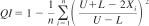
where:
Xi = values of the parameter measured,
U = allowable upper limit of X,
L = allowable lower limit of X, and
n = number of data points used to calculate QI.
Where missing data or Bad Quality Data (BQD), or both, are encountered, calculate the adjusted Quality Index (QIADJ) using the following equation:
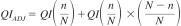
where:
Q = QI calculated without missing/BQD,
I = points,
n = number of data points used to calculate QI, and
N = number of data points for a complete data set.
If the QI calculation of a controlled parameter is less than zero, investigate the reason, assess its impact on test operational validity, and document such finding in the final test report. For calibration tests, review the operational validity assessment with the TMC.
6.3.2 Test Stand Configuration - Mount the engine on the test stand similar to its vehicle orientation (tilted up 5.5° in front; sideways 10° up on intake manifold side; bottom of oil sump horizontal). This orientation is important to the return flow of oil in the cylinder head, and ensures reproducible oil levels. Directly couple the engine flywheel to an eddy-current dynamometer through a driveshaft. The driveshaft design shall minimize vibration at the test operating conditions. The dynamometer system shall have inertia of 0.75 kg·m2 +/- 0.15 kg·m2 to ensure satisfactory control of engine speed at 800 r/min, stable air-to-fuel ratio control, and enable reproducible transient control of engine speed and torque during stage changes. Do not use hydraulic type dynamometers, as they exhibit residual torques at low speed operation. Do not use the engine to drive any external engine accessory. Recommend the area above and to the left of the rocker arm cover be left unobstructed to allow for easier on-site replacement of valve-train wear parts while the engine rests on the test stand. See Annex A9 for Safety Precautions.
6.3.3 Dynamometer Speed and Torque Control System - To improve laboratory reproducibility for transient control of engine speed and torque, the driveline system inertia, excluding engine, shall be 0.75 kg·m2 +/- 0.15 kg·m2. Control the engine power for evaluating the lubricant in a repeatable manner by:
6.3.3.1 Measuring and controlling engine speed and dynamometer torque,
6.3.3.2 Controlling exhaust absolute pressure by exhaust pipe throttling, and
6.3.3.3 Controlling the supply of intake air temperature, humidity, and pressure differential above barometer pressure.
NOTE 3 - The dynamometer speed and torque control systems shall be capable of maintaining the steady state operating set points within the performance envelope (that is, quality index established by the industry matrix testing program).
NOTE 4 - Two types of full closed-loop speed and torque control systems have been successfully utilized. One typical closed-loop system maintains speed by varying dynamometer excitation and maintains torque by varying the engine throttle. This arrangement may provide satisfactory steady-state control. Another closed-loop speed and torque control system maintains torque by varying dynamometer excitation and controls speed using the engine throttle. This arrangement may provide satisfactory transient control during stage changes.
6.3.4 Intake-air Supply System - The supply system shall be capable of delivering a minimum of 600 L/min (2000 L/min preferred) of conditioned and filtered air to the test engine during the 100 h test, while maintaining the intake-air parameters detailed in Annex A5. A humidifying chamber controls the specific humidity and provides a positive air pressure to an intake air supply duct. Annex A7 shows a general schematic of the intake air system.
6.3.4.1 Induction Air Humidity - Measure the intake air specific humidity in the main system duct or at the test stand. If using a main system duct dew point temperature reading to calculate the specific humidity, verify the dew point periodically at the test stand. Maintain the duct surface temperature above the dew point temperature at all points downstream of the humidity measurement point to prevent condensation and loss of humidity level.
6.3.4.2 Intake Air Filtering - Use the production intake air cleaner assembly (Annex A6), with filter, at the engine. Use a snorkel adapter, functionally equivalent to that shown in Annex A7, to connect the controlled air duct to the air cleaner. Modify the top of the air cleaner assembly for the installation of the intake temperature sensor and for the intake pressure sensor line. Refer to 6.3.4.5.
6.3.4.3 Intake Air Flow - Do not measure for intake airflow.
6.3.4.4 Intake Air Temperature - For final control of the inlet air temperature, install an electric air heater strip within the air supply duct. The duct material and heater elements design shall not generate corrosion debris that could be ingested by the engine. To provide sufficient duct flow for adequate air temperature control, it is recommended that excess air be dumped just prior to the air cleaner snorkel. An air dump area of approximately 60 mm2 will provide sufficient flow without stagnation. If additional airflow is required to stabilize air temperature, it is permissible to install a nominal 10 mm bleed hole in the air filter housing. Install the inlet temperature sensor in the air cleaner, centered at the inlet to the air cleaner (see Annex A7). Attach a support brace to the air cleaner assembly mounting stud and wing nut, if vibration of the temperature sensor is a problem.
6.3.4.5 Intake Air Supply Pressure - Install a disc type valve in the controlled air system supply duct to control the engine inlet air gage pressure. Locate the sensing tube for inlet air pressure in the topside of the air cleaner assembly (50 mm +/- 10 mm left and 80 mm +/- 10 mm in front of the right rear corner of the assembly). This location senses the pressure before the air enters the air cleaner element.
6.3.5 Fuel Supply System - This test method requires approximately 200 L of unleaded Haltermann KA24E Green test fuel per test (100 cycles). Ensure a sufficient fuel supply at the start of test to conduct the test without a shutdown. Use the production port fuel injection system, including fuel pump (see Annex A7), fuel injector rail, and fuel pressure regulator. Use recirculated fuel within the system using a non-production heat exchanger to maintain fuel temperature ranging from 15 °C to 30 °C. Measure fuel consumption using a mass flow meter (MicroMotion model D-6 is suitable). Install a fuel filter assembly (see Annex A7) upsteam of the fuel pump. Ensure proper fuel filtration to maintain precise air-fuel ratio control during the test.
6.3.5.1 Fuel Temperature - Measure fuel temperature through one of the ports in a cross fitting located in the line between the fuel pump and the fuel rail. Maintain the fuel temperature to the fuel rail below 50 °C.
6.3.5.2 Fuel Pressure - Measure the fuel pressure through one of the ports in a cross fitting located in the line between the fuel pump and the fuel rail inlet.
6.3.5.3 Fuel Flow - Install a mass fuel flow meter for measuring the fuel consumption rate in the fuel supply system, prior to the fuel recirculating loop. A MicroMotion model D-6 fuel flow meter has been found to be suitable.
6.3.6 Exhaust System - Use a production cast iron exhaust manifold, without insulation, for the test.
6.3.6.1 Plug the rear of the manifold (EGR supply) with a pipe fitting. Do not use an EGR for this test.
6.3.6.2 Use and install a production exhaust gas oxygen sensor (one-wire EGO) in the original location in the exhaust manifold.
6.3.6.3 Mount an industrial cooling blower with a nominal air flow rating within 10000 L/min to 14 000 L/min to blow air vertically over the cast iron exhaust manifold and the manifold exhaust gas oxygen (EGO) sensor. This cooling air is essential to proper EGO operation. Ensure this cooling air is not directed to the engine oil pan or rocker arm cover. Use a deflector shield to prevent air currents at the oil pan. See Annex A9 for Safety Precautions.
6.3.6.4 Use the production exhaust pipe front length (minimum 500 mm), including tube collector with shield, leading from the manifold. Route the exhaust from the test cell using accepted laboratory practices. Install an exhaust pressure control valve at any point after the production exhaust pipe to enable the exhaust to be controlled to an absolute pressure. Use of a catalytic converter, or exhaust attenuator, or pipe cooling is optional, provided these devices are installed after the production exhaust pipe front length and specified absolute pressure is maintained. Remove the unused exhaust pipe production fitting, and weld a plate over the opening (see Annex A7).
6.3.6.5 Because this test method is continuously operated at low engine speeds and torque, the water vapor in the exhaust gas tends to condense in the exhaust piping. Install a low point drain in the exhaust piping to remove accumulated water before the start of each test. Depending on the exhaust piping arrangement, if exhaust pressure fluctuations are observed, remove water periodically throughout the 100 h test.
6.3.6.6 Air-To-Fuel-Ratio Sensor - Install a Universal Exhaust Gas Oxygen (UEGO) sensor in the production exhaust pipe to monitor the air-to-fuel ratio. Make a port 30 mm +/- 10 mm downstream of the collector. Orient the UEGO to the front side of the exhaust pipe using the appropriate weld fitting. It is not necessary to direct cooling air over the UEGO sensor.
6.3.6.7 Exhaust Gas Temperature - Measure the exhaust gas temperature using a 6 mm diameter thermocouple. Install the thermocouple in a welded fitting attached to the exhaust pipe at a location 50 mm +/- 10 mm downstream from the end of the collector. Insert the sensor tip to the center of the exhaust pipe (see Annex A7).
6.3.6.8 Exhaust Absolute Pressure - Attach the exhaust pressure sensor tube to a welded fitting installed on the exhaust pipe at a location (50 +/- 10) mm downstream from the end of the tube collector. Orient this fitting circumferentially 60° to 90° from the exhaust temperature sensor.
6.3.6.9 Exhaust Sample Probe - It is optional to install an exhaust sampling probe for emission analyses (percent O2, CO2, CO, HC). If used, locate the exhaust sampling probe 100 mm downstream from the end of the collector on the exhaust pipe. Extend the probe into the center of the exhaust pipe, with the tip of the probe cut to a 45° angle (longest portion facing upstream).
6.3.7 Air-to-Fuel Ratio Control - Control the air-to-fuel ratio (AFR) at a stoichiometric mixture (14.4 +/- 0.3) by the engine ECM, using feedback from the production exhaust gas oxygen sensor installed in the exhaust manifold.
6.3.7.1 AFR Measurement - To monitor the reliability of the AFR control, use an AFR analyzer with a separate wide range-sensing element (UEGO) sensor to compute the AFR. Use a Horiba model MEXA 110 lambda analyzer, or the ETAS Lambda Meter LA3. These analyzers are configured to read directly the air-to-fuel ratio. Program the Mexa 110 AFR analyzer with the information shown in Table 4 for the Haltermann KA24E Green test fuel. Input the Mexa 110 analyzer with sensor calibration documentation received with the sensor. It is recommended that a periodic verification of the calibration be performed by exposing the sensor to a 4.0 % O2, N2 balance certified gas. Follow the manufacturer's calibration procedures for the AFR analyzer used.
6.3.8 Ignition System - Do not modify the ignition system for this test method.
6.3.8.1 Monitoring Ignition Timing - Use an automotive timing light (strobe) to visually check the ignition timing.
6.3.9 Engine Coolant System - A schematic diagram of the external coolant system is shown in Annex A7. Use a 50 % deionized water and antifreeze solution, using an extended life ethylene glycol based engine coolant. Texaco Havoline DexCool has been found to meet this requirement (see Annex A8). Configure the plumbing such that the total coolant system capacity, including engine and normal reservoir capacity, is 25 L to 30 L. Regulate the system pressure by a 100 kPa radiator-type pressure cap onto the reservoir tank. Plumb the coolant to enter the engine at the thermostat housing (remove the thermostat). Coolant exits the engine at the front of the intake manifold. Circulate a portion of the engine coolant through the specially manufactured jacketed rocker cover (see Annex A7).
6.3.9.1 External Coolant Pump - Use an electric motor-driven centrifugal bronze body pump with a nominal minimum rating of 150 L/min at 100 kPa head pressure. The actual flow range during the test (including break-in) is 20 L/min to 70 L/min.
6.3.9.2 Coolant Heater - Use a nominal 8 kW electric heater, or equivalent external heating source, in the coolant system. This allows engine coolant soak temperatures to be maintained while the engine is not running. Because the ECM coolant temperature sensing system is non-operable, smooth running of the engine upon start-up depends on maintaining the coolant soak temperature.
6.3.9.3 Coolant Heat Exchanger - Use a conventional shell-and-tube heat exchanger for cooling. Flow the engine coolant through the tube side, and use process water on the shell side. A nominal 150 mm diameter by 1200 mm long exchanger has been found to be suitable. Position the heat exchanger vertically, and the coolant inlet at the top of the exchanger. Plumb the high point bleed to remove system air during initial circulation of coolant. Install a sight-glass in the coolant line upstream of the external coolant pump. Plumb a low point drain to allow complete coolant removal.
6.3.9.4 Coolant Control - For control of the coolant out temperature, install an automatic control valve in the process water outlet of the heat exchanger. Use a control valve with a Cv rating of 1.25 for the recommended heat exchanger size.
6.3.9.5 Coolant Flow Control - Measure the coolant flow using a volumetric flow sensor installed in the coolant line between the heat exchanger and the coolant inlet to the engine. A Barco venturi metering element is recommended. Control the flow by an automatic flow control valve on the discharge side of the external pump. A control valve with a Cv rating of 16 is recommended.
6.3.9.6 Jacketed Rocker Cover Coolant System - Route a portion of total coolant system flow through the jacketed rocker cover. Install a tee fitting at the exit of the coolant heat exchanger to allow the coolant flow to split into two circuits (main circuit to the engine thermostat housing and secondary circuit to the jacketed rocker cover (see Fig.2). The secondary circuit enters the front of the jacketed cover and exits the rear of the cover. Install an automatic air bleed vent near the front of the rocker cover. Limit the secondary circuit flow rate at the exit by installing a two-way control valve, 13 mm nominal internal diameter size, with a flow coefficient rating (Cv) of 1.25. Configure the control valve in the fail-safe open position. The secondary flow joins the primary flow at the suction of the coolant system-circulating pump. Refer to the schematic of the cooling system located in Annex A7.
6.3.10 Crankcase Ventilation System (Fig.3) - Alter the Nissan production routing of the crankcase gasses to ensure that a certain mass flow rate of fresh air is supplied to the valve-train underneath the jacketed rocker cover. Take humidity-conditioned air from the bottom, left rear of the air cleaner housing and route to the rear right side of the rocker arm cover and to the engine front cover.
6.3.10.1 Draw the crankcase off-gas from the engine at the production breather and oil separator. From the breather, the crankcase gas flows through the Positive Crankcase Ventilation (PCV) valve to the bottom plenum of the intake manifold (see Annex A7) for a drawing of the ventilation system plumbing.
6.3.10.2 Use a mass flow meter to measure the fresh airflow to the rocker cover of 10.0 L/min (SLPM, Standard Litres per Minute). This meter, corrected to standard conditions, shall have an accuracy of +/- 0.25 L/min (SLPM) at 10 L/min (SLPM). Full scale of the meter shall be a minimum of 20 L/min (SLPM). Time response of the measurement shall be less than or equal to 1.0 s. One model that meets these specifications is Sierra Mass Flow Meter, model 730-N2-1E0PV1V4 (air; 20 SLPM).
6.3.10.3 Prior to the meter, install a three-way control valve having a nominal size of 13 mm and a flow coefficient rating of 2.5 Cv. Configure the valve so that loss of control power routes all air to the rocker cover. A Badger Meter 1/2 in. research valve with Trim A meets these requirements. Use a 20 L nominal surge at the exit of the flow meter.
6.3.10.4 The plumbing from the 3-way valve to the engine front cover is a nominal diameter of 10 mm; see Fig.4. The plumbing from the 3-way valve, through the flow meter and surge chamber, and on to the rear of the rocker cover, is a nominal diameter of 16 mm. A 3.2 mm needle-valve may be installed between the intake and the PCV.
6.3.10.5 Diversion for Blowby Measurement - To facilitate the periodic measurement of engine blowby, install a 3-way valve in the hose between the engine PCV and the intake manifold vacuum source. Use a longer hose to connect the rocker cover to the air cleaner housing. During blowby measurement, position the 3-way valve and hoses to route blowby from the rocker cover (bypassing the air cleaner), through the blowby meter, through the 3-way valve, then to the intake manifold vacuum source. Monitor crankcase pressure at the dipstick tube. During blowby measurement, adjust the blowby measurement apparatus for zero crankcase pressure.
6.3.11 Temperature Measurement - Temperature measurement equipment and locations for the required temperatures are specified in 6.3.11.1 - 6.3.11.7. The TMC shall approve alternative temperature measurement equipment. The accuracy and resolution of the temperature measurement sensors and the complete temperature measurement system shall follow the guidelines in Specification E230.
6.3.11.1 Thermocouples - All thermocouples except the intake-air thermocouple shall be premium, sheathed, types with premium wire. The intake-air and ambient air thermocouples may be an open-tip type. Grounded thermocouples may provide a more accurate reading, in situ, when immersion depths are limited. Using grounded thermocouples requires the incorporation of signal conditioning modules for providing electrically isolated inputs to digital computer systems. Use thermocouples of 3.2 mm or 6.4 mm diameter in specific locations. The 3.2 mm thermocouples are specified at locations, which require short immersion depths to prevent undesirable temperature gradients. For exhaust gas temperature, the 6.4 mm diameter thermocouple is recommended. Match thermocouples, wires, and extension wires to perform in accordance with the special limits of error as defined by Specification E230. Either Type J (Iron-Constantan) or Type T (Copper-Constantan) or Type K (Chromel-Alumel) thermocouples are acceptable; Type J is preferred.
6.3.11.2 Resistance Thermometer Detectors - Do not use Resistance Thermometer Detectors (RTDs) as alternatives to thermocouples, due to inherent signal attenuation characteristics that are different from sheathed, grounded thermocouples.
6.3.11.3 Engine Coolant Inlet - Install the engine coolant inlet temperature sensor at the inlet pipe, 200 mm +/- 20 mm from the end of the thermostat-housing nipple. Locate the sensor tip at the center of the pipe inner diameter.
6.3.11.4 Engine Coolant Outlet - Install the engine coolant outlet temperature sensor at the coolant water outlet passage at the front end of the intake manifold. Locate the existing port at the top of the manifold, 50 mm +/- 10 mm from the intake gasket surface. Locate the sensor tip in the center of flow. The recommended thermocouple diameter is 3.2 mm. This temperature is the coolant control point.
6.3.11.5 Engine Oil Gallery Temperature - Precisely weld a thermocouple fitting to the oil filter block (see Fig.5). A 3.2 mm diameter thermocouple, or equivalent is recommended. Position the sensor tip in the center of the oil passageway. Do not use the engine oil gallery temperature for oil temperature control.
6.3.11.6 Engine Oil Sump Temperature - Sense the engine oil sump temperature by modifying the drain plug location of the oil pan for a thermocouple fitting, as shown in Fig.6. Insert the sensor tip 50 mm +/- 5 mm inside the interior surface of the oil pan. Only monitor this temperature. It is not used for oil temperature control.
6.3.11.7 Cylinder Head Oil Temperature - Assess the cylinder head oil gallery from the intake side of the head through the vertical passage, centered front-to-rear (see Fig.7). Drill an access port in a bossed area of the head, and locate 10 mm upward from the deck surface of the head. Drill and tap the access port to accept a 3.2 mm close pipe nipple. Connect a 3.2 mm pipe tee to the nipple. Use a straight-through tee connection for the temperature sensor. Insert the sensing tip into the center of the oil gallery passage. Orient the right angle tee connection downward and use for the measurement of cylinder head gallery pressure. The cylinder head oil temperature is the primary control point.
6.3.11.8 Dynamometer Load Cell Temperature - Measure the dynamometer torque using a strain-gage transducer attached to the moment arm; it is recommended that the environment surrounding the transducer be maintained at a constant temperature. Strain-gage transducers are very sensitive to temperature changes. Use a temperature sensor located near the transducer to monitor ambient variations.
6.3.11.9 Rocker Cover Inlet and Outlet Temperature - Measure the rocker cover inlet and outlet temperature within 150 mm of the inlet and outlet connections. Install the sensor tip in the center of flow.
6.3.11.10 Rocker Cover Gas Temperature - Insert the rocker cover gas temperature sensor through the rear cylinder head rubber gasket (half moon rubber plug). Drill a 2 mm diameter hole in the rear rubber plug, 4 mm down from the top, flat surface, centered horizontally. Press fit a 3.2 mm diameter closed tip type J thermocouple, 4 cm length, into the drilled hole so that the tip of the sensor is 12 mm from the inside surface of the rubber plug.
6.3.12 Pressure Measurement Equipment - The seven required pressure measurement parameters are shown in 6.3.11.2 - 6.3.11.7. This test method does not specify specific measurement equipment. This allows reasonable opportunity for adaptation of existing test stand instrumentation. The accuracy and resolution of the pressure measurement sensors and the complete pressure measurement system shall follow the guidelines detailed in ASTM research report RR:D02-1218.
6.3.12.1 Allowance for Pressure Head Deviations - Use tubing between the pressure tap locations and the final pressure sensors and incorporate condensate traps. This is important in applications where low air pressures are transmitted through lines passing through low-lying trenches between the test stand and the instrument console. Locate the pressure transducer at the same elevation as the measurement location, or account for the pressure head. Design the oil pressure sensor/tubing lines to minimize the trapped oil volume in the tubing lines.
6.3.12.2 Intake Manifold Vacuum - Measure the intake manifold vacuum on the throttle body, at an existing port located just below the throttle plate.
6.3.12.3 Engine Oil Pressure - Sense the engine oil pressure at the production location on the oil filter block (see Fig.5). Route the sensing line to a tee fitting, allowing ports to a pressure transducer and an analog pressure gage.
6.3.12.4 Cylinder Head Oil Gallery Pressure - Assess the cylinder head oil gallery from the intake side of the head through the vertical passage, centered front-to-rear. Drill this access port in a bossed area of the head that is located 10 mm upward from the head deck surface. Drill and tap the access port to accept a 3.2 mm close pipe nipple. Connect a 3.2 mm pipe tee into the nipple. Orient and use the right angle tee connection downward for the measurement of cylinder head gallery pressure.
6.3.12.5 Fuel Pressure - Measure the fuel pressure through a cross-fitting port located in the line between the fuel pump and the fuel rail inlet.
6.3.12.6 Crankcase Pressure - Attach the crankcase pressure sensing line to a fitting welded to the dipstick tube. Locate this fitting approximately (80 +/- 10) mm from the top of the dipstick tube (see Fig.8). The sensor shall be capable of measuring positive and negative pressure. If using a manometer, install a liquid trap to prevent manometer fluid from entering the crankcase.
6.3.12.7 Coolant Pressure - Attach the coolant pressure sensing line to a fitting welded to the coolant reservoir.
6.3.13 Flow Rate Measurement Equipment - Measure the engine coolant, fuel, and blowby flow rate. The accuracy and resolution of the flow rate measurement sensors and the complete flow rate measurement system shall follow the ASTM research report RR:D02-1218.
6.3.13.1 Engine Coolant Flow Rate - Determine the engine coolant flow rate by measuring the differential pressure drop across a venturi flowmeter. A Barco #70523 is suitable. Calibrate a differential pressure transducer to provide an output (litres per minute). Take precautions to prevent air pockets from forming in the lines to the pressure sensor. Transparent lines or bleed lines, or both, are beneficial in this application.
6.3.13.2 Fuel Consumption Rate - Determine the fuel consumption rate using a mass flow meter installed in the makeup fuel line. The flow meter output shall allow real-time measurement of fuel rate (kilograms per hour) and total fuel consumed (kilograms). A MicroMotion Model D-6 is satisfactory.
6.3.13.3 Blowby Flow Rate Measurement System - Use the apparatus shown in Annex A7 for measurement of the blowby flow rate. The measurement system routes the blowby through an external, sharp-edge orifice and into the engine intake manifold by way of an auxiliary PCV valve. Maintain the crankcase gage pressure at 0.0 kPa to 0.025 kPa during system operation to minimize crankcase leakage. Determine the blowby flow rate by measuring the differential pressure drop across the sharp-edge orifice. Use an inclined manometer or differential pressure sensor for the orifice differential pressure measurement. The crankcase pressure sensor shall have a 0 kPa to 1 kPa range and be adequately damped to indicate a zero gage pressure. The sharp-edge orifice is specifically designed for blowby flow rate measurement and shall be fabricated in strict compliance with the specifications available from the TMC. The assembly contains five orifices. Use a 3.175 mm orifice for the blowby flow rate range of 5 L/min to 12 L/min. The flow rate measurement orifice fabrication location and the blowby flow rate measurement can be obtained from the TMC.
6.3.14 Process Cooling Water - Provide the engine jacket coolant heat exchanger, the oil cooler, and the eddy-current dynamometer with process cooling water to maintain proper operating temperatures.
6.3.14.1 Dynamometer Cooling System - Water-cool the eddy current electric dynamometer. Provide provisions for automatic test shutdown in the event the dynamometer cooling water is shut off.
6.3.15 Volumetric Graduates - Use volume to measure the test oil quantity. Do not use mass, converted to a calculated volume. Recommend using a 1000 mL graduate and 500 mL graduate for volumetric determinations. All volumetric graduates shall be accurate to 2 % of full scale. The large graduate resolution shall be 100 mL, and the small graduate resolution shall be 25 mL.
6.4 Test Engine Hardware - This section specifies the hardware required to build the test engine. Conduct the engine break-in procedure prior to the first test on a long block and on the first test when a cylinder head is replaced. The new engine is a long-block, as received. Use the camshaft and rocker arms in the new engine for break-in purposes only. Remove and modify the new cylinder head for the cylinder head oil gallery temperature and pressure measurement port, and for valve spring force calibration. Clean and reassemble the head using the break-in camshaft and rocker arms. Use the break-in procedure shown in 11.1.3. After break-in, replace the break-in camshaft and rocker arms with the new camshaft and rocker arms parts.
6.4.1 Nissan Supplied Component Kits - Obtain the test parts and engines for this test method from Nissan North America 11,12 (see Annex A6).
6.4.1.1 TestEngine Long-Block - Order the test engine long-block assembly (also called bare engine assembly) as shown in Annex A6. The test engine includes the block, pistons, rods, crankshaft, oil pan, front cover, cylinder head, and rocker arm cover final assembly. Use the camshaft and rocker arms during engine break-in only; but they are not official test parts. Annex A6 contains information regarding the number of test the short-block may be used. Use the original cylinder head for the number of test listed in Annex A6.
6.4.1.2 Stand Set-Up Kit - There are four component kit parts that comprise the stand setup kit (see Annex A6). These four component kits include crankshaft pulleys, flywheel, intake and exhaust manifolds, air cleaner, fuel injection system, EGR block-off plate, ignition distributor, wiring, starter motor, fuel pump, exhaust pipe, and oil cooler. Use one of each of the four component kit parts to configure one test installation.
6.4.1.3 Test Kit - For every official test conducted, use one test kit. This kit includes a camshaft, two rocker shafts, twelve rocker arms, three oil filters, and four spark plugs. The test kit camshaft and rocker arms are considered critical test parts. Do not substitute critical test parts with any other dealer, or aftermarket supplied hardware. Do not alter or modify any test kit part from as-received condition unless expressly approved by the surveillance panel. If any test kit part is modified, note that in the comment section of the test report.
6.4.1.4 Cylinder Head Replacement Kit - Every engine short-block is used for the number of tests listed in Annex A6. Use the original cylinder head for the number of tests listed in Annex A6. After that number of tests, install a replacement cylinder head for the number of runs listed in Annex A6. To assemble and install the bare cylinder head, use 1 gasket and seal kit. Install new calibrated valve springs, intake and exhaust valves with the replacement head (see Annex A6). When the replacement head is installed onto the engine, use the original supplied camshaft and rocker arms for conducting another break-in prior to the next test.
6.4.2 Procurement of Critical Parts - The test camshaft and rocker arms are critical engine parts for this test method. Obtain these parts by annual orders placed through Nissan North America. Do not use dealer, service, or aftermarket camshafts and rocker arms for this test method. Do not alter or modify any critical part from as-received condition unless expressly approved by the surveillance panel. If any critical part is modified, note that in the comment section of the test report.
6.4.3 Required New Engine Parts - This test method is a flush-and-run type test. For each test, the camshaft and rocker arms are replaced. Use all the parts in test kit number 13000-40F85 as shown in Annex A6.
6.4.3.1 Replace the spark plugs for each test, just prior to the oil flush (see 9.7.2). Gap the spark plug at 0.99 mm.
6.4.4 Reusable Engine Parts - Replace the engine short-block and the cylinder head as specified in Annex A6. If the engine demonstrates deterioration (excessive blowby or oil consumption or fuel dilution, poor compression, low oil pressure, clearances beyond service limits, or stripped fasteners) prior to this expected life (see Annex A6), replace the engine and follow the break-in procedure prior to resuming non-reference oil testing. Do not exceed the number of tests on the short-block or cylinder heads listed in Annex A6.
6.4.4.1 Replace the PCV valve, fuel filters, rocker cover gaskets, and air filter element whenever the cylinder head, or engine, or both are replaced. The ignition distributor can be used as long as it remains serviceable. Distributor cap (Nissan Part Number 22162-40F00) and rotor (Nissan Part Number 22157-21E01) can be replaced as needed.
6.4.4.2 Reuse the jacketed rocker arm cover, oil pan, oil cooler, flywheel, intake and exhaust manifolds, throttle body, modified dummy water pump, spark plug wires, fuel injection system components, and engine sensors, as long as they continue to function properly.
6.5 Special Measurement and Assembly Equipment - This section describes the special apparatus, tools, and equipment required for engine measurement and assembly. Routine laboratory and workshop items are not included. Specific engine tools are shown in Table 5.
6.5.1 Camshaft Lobe Measurement Equipment - Trace the camshaft lobes with a surface texture profilometer system.
6.5.1.1 Use a surface measurement profilometer with real time digital display and graphical output capability. The vertical scale graphical resolution shall be capable of 1 µm per graph division. The profilometer shall be capable of traversing at least 100 mm, with a straightness accuracy equal to or less than 1 mm per 100 mm of traversed length.
6.5.1.2 Use the profilometer pickup without a skid. Use a conical or spherical diamond tip stylus, with a nominal radius of 5 µm.
6.5.1.3 The nominal traversing speed is 0.50 mm/s to 0.75 mm/s. A computer interface is recommended. The Precision Devices, Inc. MicroAnalyzer 2000 system, see Fig.9, a computer-driven profilometer, may be used. Equip the profilometer with custom V-blocks (see Annex A6) for holding the work-piece (the camshaft on its journals), and an optical angle encoder for determining the cam shaft angular position (see Annex A6).
6.5.1.4 View the data from the trace in the profile mode, allowing an analysis of the texture and waviness of the trace. Configure the instrument software for a two-point line texture leveling at the unworn edges of the cam lobe. Use this reference line for wear measurements. Display the profile waviness, using the Gaussian smoothing filter, set at 0.25 mm cutoff length, and do not remove the filter width at the ends of the texture.
6.5.1.5 Base the lobe wear measurement upon the vertical dimension between the horizontally positioned, twp-point leveling line (reference line) and the lowest point in the waviness profile.
6.5.2 Unassembled Valve Spring Calibration Device - Use a device to screen inner and outer valve springs before assembly in the cylinder head. Measure the individual spring forces at various compressed heights according to the Nissan Service Manual. The tester shall be accurate to 2 % and a resolution of 5 N.
7. Reagents and Materials
NOTE 5 - Use 13 L of the non-reference test oil sample to perform the 100 h Valve-train Wear test.
7.1 Coolant for Engine and Rocker Arm Cover - Demineralize (less than 0.29 g/kg) the coolant or use distilled water mixed with an extended-life ethylene glycol antifreeze/coolant at a 50:50 ratio.
7.2 Fuel - Use Haltermann KA24E Green test fuel for this test method as shown in Annex A8. (Warning - Flammable. Health hazard.) It is dyed green to preclude unintentional contamination with other test fuels. Use approximately 200 L of fuel for each test (100 cycles). This fuel has a hydrogen-to-carbon ratio of 1.80 to 1.
7.2.1 Fuel Approval Requirements - The fuel is blended as needed by the fuel supplier. Base the fuel batch acceptance upon the physical and chemical specifications given in Annex A8. Engine validation tests are not necessary for fuel batch acceptance.
7.2.2 Fuel Analysis - Monitor the test fuel using good laboratory practices. Analyze each fuel shipment to determine the value of each parameter for existent gum as described in Test Method D381, RVP as described in Test Method D323, and API Gravity as described in Test Method D287. Compare the results to the original values supplied by the fuel supplier. The analytical results shall be within the tolerances shown in parentheses beside each parameter. This provides a method to determine if the fuel batch is contaminated or has aged prematurely. Ifany analytical result falls outside the tolerances, the laboratory shall contact the fuel supplier for problem resolution.
7.2.2.1 Fuel Deterioration - Analyze the fuel semiannually to ensure the fuel has not deteriorated excessively or been contaminated in storage.
7.2.2.2 Analyze the fuels using Test Methods D287, D323, D381, and D525.
7.2.3 Fuel Shipment and Storage - Ship the fuel in containers with the minimum allowable venting as dictated by all safety and environmental regulations, especially when shipment times are anticipated to be longer than one week. Store the fuel in accordance with all applicable safety and environmental regulations. If the run tank has more than one batch of fuel, document the most recent batch in the test report. Do not top-off the run tank with the new fuel batch unless the tank is less than 10 % full.
7.3 Lubricating Oils:
7.3.1 Break-in Lubricating Oil - An engine break-in procedure (see 11.1.3) is immediately conducted following the replacement of new, major engine components (that is, engine short-block, or cylinder head, or both). Use the proper reference oil, REO 926-2, from the TMC for the break-in procedure. Use approximately 3.5 L of this reference oil for each break-in procedure.
7.3.2 Lubricant for Hydraulic Lash Adjusters - The rocker arms hydraulic lash adjusters may ingest air during shipping and handling. Prior to installing the rocker arms in the test engine, prime the lash adjusters with an SAE 20 API SA grade oil, as shown in SAE J183. Place the rocker arms on their side, for a minimum of 1 h, in a container filled with the SA grade oil to allow trapped air to bleed out. If using a vacuum chamber, reduce the minimum soak time to 5 min. Immediately install the rocker arms in the engine after the rocker arms are removed from the oil-filled container. Do not allow the rocker arms to lie on their side after air has been bled.
7.3.3 Short-block Assembly Lubricant - For engine short-block inspection and reassemble, use SAE 20 API SA grade oil as the assembly lubricant.
7.4 Miscellaneous Materials:
7.4.1 Solvents and Cleansers - No substitutions for 7.4.1.1 - 7.4.1.3 are allowed. Use adequate safety provisions with all solvents and cleaners.
7.4.1.1 Solvent - Use only mineral spirits meeting the requirements of Specification D235, Type II, Class C for Aromatic Content (0 vol % to 2 vol %), Flash Point (61 °C, min) and Color (not darker than +25 on Saybolt Scale or 25 on Pt-Co Scale). (Warning - Combustible. Health hazard.) Obtain a Certificate of Analysis for each batch of solvent from the supplier.
7.4.1.2 Pentane - (Warning - Flammable. Health hazard.) Available from petroleum solvent suppliers.
7.4.1.3 Cylinder Block and RAC Cleaning Detergent - Trisodium phosphate and any commercial coolant cleanser. (Warning - Caustic. Health hazard.)
7.4.2 Sealing Compounds - Use a silicone based gasketing compound during engine assembly (for example, oil pan). Use only the silicone gasket shown in Annex A6.
8. Oil Blend Sampling Requirements
8.1 Sample Selection and Inspection - The non-reference oil sample shall be uncontaminated and representative of the lubricant formulation being evaluated.
NOTE 6 - If the test is registered using the American Chemistry Council protocols, the assigned oil container formulation number shall match the registration form.
8.2 Non-reference Oil Sample Quantity - Use a minimum of 13 L of new oil to complete the Sequence IVA test, including the oil flushes. Normally the supplier provides a 15 L new oil sample to allow for inadvertent losses.
8.3 Reference Oil Sample Quantity - The TMC provides a 15 L reference oil sample for each stand calibration test.