

4 General principles for the sampling of insulating liquids
4.1 New insulating liquids in delivery containers
4.1.1 Place of sampling
The sample shall be taken from the part of the delivery container where the insulating liquid is likely to be most heavily contaminated. To evaluate the quality of a consignment, two types of samples may be normally taken:
a) composite sample: mixture of samples taken at the same level in several containers;
b) individual sample: sample or mixture of samples taken at the same level in one container.
From a delivery, individual samples of 1 l may be taken from different containers for the electric strength test. Further tests may be carried out on these samples and a complete examination on the mixture of these (composite sample).
In certain cases, it may be useful to constitute an average sample within the container. An average sample is a mixture of samples taken at different levels in one container.
1) tankers: samples should be taken from each tanker as described in 4.1.4.2 below;
2) drums: samples should be taken as described in 4.1.4.3 below.
In the case of a single drum, this shall be sampled.
In case there is more than one drum of a lot of oil, sampling procedures should be negotiated between supplier and user. For example, samples can be taken from 10 % of drums or at least 2 drums, whichever the largest.
4.1.2 Quantity of sample to be taken
This depends on the tests to be performed and the procedures used.
Typically, 2 l are taken.
4.1.3 Sampling equipment
4.1.3.1 General
Since the results of the tests included in IEC requirements for insulating liquids can greatly depend on the impurities in the sample, it is essential to observe the following precautions:
- separate sampling equipment shall be reserved exclusively for each type of liquid. All seals and tubing used should be compatible with the insulating liquid to be sampled;
- the equipment shall be clean and dry, following the cleaning procedures described in 4.2.1.6. Particular care should be taken to ensure the absence of any traces of solid impurities, such as dust, fibres, etc. The use of rags for cleaning is not permitted.
4.1.3.2 Sampling probes
As examples, four types of sampling probes are described below. Other probes may also be used, provided they do not introduce any contamination. Stainless steel and aluminium are suitable.
a) Sampling from tankers
The thief dipper shown in Figure 1 is suitable for taking samples at the bottom of the container. This is a dipper constructed of stainless steel or aluminium tubes and castings, machine-finished all over. It shall be sufficiently heavy to sink in the liquid. It should always be suspended by means of a metal wire or chain. String or other fibrous materials shall not be used.
The cream dipper is used for taking top samples of insulating liquids. This probe shall be constructed as shown in Figure 2 and shall be of stainless steel.
b) Sampling from drums
The pipette shown in Figure 3 enables samples to be taken at the bottom of drums. This pipette has a capacity of about 500 ml.
Another probe to take samples at the bottom is shown in Figure 4; it is a siphon with a glass, stainless steel or aluminium tube having an internal diameter of about 13 mm for taking off the sample liquid, and a metal tube (internal diameter 5 mm) for applying pressure. Both tubes are set in an oil-resistant bung whose dimensions correspond to the diameter of the bung hole in the drum. Commercial versions of this equipment are available. When possible, glass is preferable for probes illustrated in Figures 3 and 4.
The cream dipper (Figure 2) may be used for taking top samples.
4.1.3.3 Sample containers
For storing and transporting samples, depending on the oil test to be performed, sample containers of appropriate volume shall be used. Different types of sample containers are indicated in 4.2.1.5.
For the mixing of different samples, a special sample container made of glass with a capacity of at least 6 l shall be used. These special sample containers shall be closed in a manner that allows them to be sealed, by means of oil-resistant plastic or compatible rubber tubing or screw caps equipped with a polytetrafluoroethylene (PTFE) lining. Natural rubber tubing and/or seals are not permitted. PTFE and polypropylene (PP) seals are acceptable.
Each sample container shall have a label on which are marked all the indications necessary to identify the contents, i.e. the markings of the drums or tanks, date of sampling and the name of the recipient.
4.1.3.4 Cleaning of sampling equipment
Sampling equipment shall be cleaned following the procedures described in 4.2.1.6.
4.1.4 Sampling procedure
4.1.4.1 General remarks
According to general principles for sampling (see 4.1.1), samples of new insulating liquid shall be taken from the bottom of the delivery container, where the contamination is likely to be the greatest. But in certain cases, an average sample is also of interest.
NOTE 1 To obtain an average sample, samples are taken at intermediate levels in tanks or drums. Examples of procedure are given in Annex A. A procedure is indicated in the NOTE in 4.1.4.2 a) for obtaining the equivalent of an average sample.
In Table 1 different cases are considered:
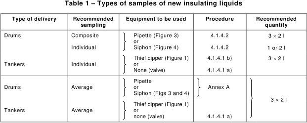
NOTE 2 Before sampling from tankers, sufficient oil should be pumped from the end of the delivery pipe, as required by 4.1.4.2.
Every precaution shall be taken during sampling in order to avoid contamination of the insulating liquids. Outdoor sampling of insulating liquids in rain, fog or high wind is only permitted if all precautions have been taken to avoid contamination of the liquid. In this special case, the use of a cover is necessary.
Condensation shall be avoided by warming the sampling equipment so as to be above the ambient air temperature. Before use, the equipment shall be rinsed with the liquid being sampled. The operator shall be warned not to permit his hands to come in contact with the surfaces of sampling equipment subsequently in contact with the oil. The insulating liquids shall be protected against light irradiation during transportation and storage.
On arrival at the laboratory, the sampling container shall not be opened immediately. It is necessary to wait until the temperature of the sample is the same as the room temperature.
4.1.4.2 Sampling from tankers
Insulating liquids may be sampled either through the tank outlet or by a thief dipper or by a cream dipper.
a) Sampling through the tank outlet
By this procedure, it is possible to obtain a sample representative of the bottom of the tank after this has been allowed to stand for at least 1 h after the vehicle has arrived.
NOTE It may be possible, by this procedure, to obtain the equivalent of an average sample, if the sampling is done directly after the vehicle has arrived.
In this case, the sampling procedure shall be as follows:
- remove the outlet valve shield, if fitted;
- remove all visible dirt and dust from the valve by means of lint-free clean cloths or oil-resistant synthetic sponges;
- the outlet system (pump, delivery pipe), if incorporated, shall be started or opened as appropriate in order to get a sample;
- open the valve and allow to flow, slowly, at least 10 l of insulating liquid into a waste oil container. In any case, discard at least an amount of oil equivalent to the volume of pipe;
- rinse sampling bottles with the insulating liquid;
- fill sampling bottles at constant flow to avoid turbulence.
b) Sampling with a thief dipper or a cream dipper
This sampling should be carried out after the tank has been allowed to stand for at least 1 h after the vehicle has arrived.
1) Procedure with the thief dipper (Figure 1) (bottom samples)
For taking bottom samples (i.e. within 1 cm to 2 cm from the bottom of the tank) the dipper is lowered until the projecting stem of the valve rod strikes the bottom of the tank. The dipper then fills. Filling is complete when no more air bubbles escape. The dipper is then withdrawn and its contents poured into the sample container (in the case of an individual sample) or into the special glass sample container for collecting and mixing the various samples taken (in the case of a composite sample). In this latter case, the sample container(s) is (are) filled with the mixture so obtained. During pouring of the liquid, avoid forming air bubbles by pouring too fast.
2) Procedure with the cream dipper (Figure 2) (top samples)
With the valve closed, fill the cream dipper by slowly immersing it in the liquid to be sampled until the rim is just below the surface of the liquid so that it will flow slowly into the dipper. Discard the first filling. Refill the dipper as above and transfer the sample to the sample container by allowing it to flow from the bottom orifice against the side of the sample container and not in a stream into the bottom of the sample container. Repeat the operation until sufficient liquid is obtained to fill the sample container (individual sample) or the special glass sample container used for mixing samples depending on the type of sample to be obtained.
4.1.4.3 Sampling from drums
Samples should be taken after the drums have been allowed to stand for at least 8 h with the bung uppermost, protected against rain and rainwater. For sampling the bottom (i.e. 3 mm up), the pipette (Figure 3) or the siphon pressure thief (Figure 4) may be used.
For taking a sample from the surface layer of the liquid, the cream dipper (Figure 2) may be used.
Examples of procedure:
a) Use of pipette (Figure 3) (bottom samples)
- block the upper orifice of the pipette with the thumb, and then immerse the pipette in the liquid to the bottom of the drum;
- remove the thumb to allow liquid to enter the pipette;
- again close the upper end of the pipette with the thumb and withdraw the pipette;
- the first filling is used for rinsing the pipette; transfer the next fillings into either a sample container (individual sample) or the special glass sample container for mixing samples (composite sample) (see 4.1 .4.2.b)) taking care not to form air bubbles during pouring the liquid.
b) Use of siphon (Figure 4) (bottom samples)
- fit the bung in which are set the riser and pressure tubes into the bung hole of the drum and ensure that this seal is airtight;
- dip the lower end of the riser tube to about 3 mm from the bottom of the drum;
- raise the pressure inside the drum by means of the air bulb;
- run off enough liquid to rinse the tube and then run off the required quantity directly into the sample container (individual sample) or the special glass sample container for mixing samples (composite sample) (see 4.1.4.2 b) taking care not to form air bubbles during pouring the liquid.
c) Use of cream dipper device (Figure 2) (top samples)
See 4.1.4.2 b).
4.1 .4.4 Sampling report
The sampling report shall give all the information necessary for identifying the sample as well as any details or special information likely to be of help to those entrusted with the tests. The type of sample (i.e. composite, individual or average sample) shall be specified. A copy of the report shall accompany each sample. The distribution of samples shall be in accordance with the agreed procedure, e.g. as given in the sales contract.
4.2 Sampling of oil from oil-filled equipment
4.2.1 General remarks
4.2.1.1 Safety and quality of sampling
The manufacturer's instructions for taking oil samples from the electrical equipment shall be followed. Particular attention shall be paid to the safety precautions to be taken.
Make sure that the oil in the energized electrical equipment is not under a negative pressure when taking an oil sample, since this could introduce air bubbles in the oil, induce electrical short-circuits in the equipment and put the sampling personnel at risk.
During sampling of oil, precautions should be taken to deal with any sudden release of oil and avoid oil spillage.
It is important to bear in mind that receiving a qualitative and a representative sample is crucial for obtaining a reliable assessment of the electrical equipment. Even the most sophisticated analytical and diagnosis methods cannot overcome faulty samples.
In all cases, oil sampling should be performed by properly and specifically trained personnel, especially for low volume equipment (e.g., instrument transformers).
4.2.1.2 Place of sampling
The selection of points from which samples are drawn should be made with care. Normally, the sample should be taken from a point where it is representative of the bulk of the oil in the equipment (for example, from the bottom oil drain valve or the oil sampling valve). It will sometimes be necessary, however, to draw samples deliberately where they are not expected to be representative (for example, in trying to locate the site of a fault, such as from the tap changer, selector switch or gas relay).
The methods described are suitable for large oil-volume equipment such as power transformers. With small oil-volume equipment, it is essential to ensure that the total volume of oil drawn off does not endanger the operation of the equipment.
NOTE 1 For transformers with two sampling valves, the following procedure should be used: open the outer valve first, followed by the second one. This is particularly important to avoid entrance of air into the transformers.
NOTE 2 When sampling from bushings or from instrument transformers or cables, the manufacturer's instructions should be followed carefully. Failure to do so may lead to serious damage and equipment failure. The oil sampling should be carried out on de-energized equipment. When sampling, precautions should be taken to deal with any sudden release of oil. Samples should be taken with the off-load equipment in its normal position in order to assess correctly the equipment condition.
Sampling by syringe is the procedure recommended for bushings by IEC subcommittee 36A. In the case of bushings fitted with a sampling point at the mounting flange, the described procedure applies.
In the case of bushings not fitted with a sampling point at mounting flange, it may be possible to take a sample from the top of the bushing. The manufacturer's instructions should be consulted to determine a suitable position. Insert one end of the sampling tube into the bushing, from the top, and connect the other end to the three-way stopcock on the syringe, using plastic coupling, then follow the same procedure.
In the case of bushings pressurized at ambient temperature, the procedure is not applicable, and reference should be made to the instructions of the equipment manufacturer.
4.2.1.3 Cleaning of sampling point
Cleaning of the sampling equipment and flushing of the sampling point shall be done to prevent contamination of oil samples.
The blank flange or cover (11) of the sampling valve in Figures 5, 6 and 7a is removed and the outlet cleaned with a lint-free cloth or oil-resistant synthetic sponge to remove all visible dirt.
The drain valve is flushed with a sufficient quantity of oil (typically, 2 l to 5 l), under a turbulent flow, to eliminate any contaminants (water and particles) that might have accumulated in the drain valve and at its orifice.
Use protection gloves, preferably made of nitrile rubber, and a bucket for waste oil. The sampling point shall be cleaned each time a new sample of oil is taken.
For measuring water content in oil, sampling shall be carried out preferably during days when the humidity of the air is as low as possible, to prevent moisture condensation on sampling equipment and contamination of the oil sample.
The temperature of oil at sampling point shall be measured with a thermometer placed in the flow of oil and indicated on the sample, to ensure the calculation of the relative humidity of oil, also recording whether or not the fans and pumps are running. In both cases, the method used to measure the temperature shall be indicated.
4.2.1.4 Connection between sampling point and sampling device
The connection between the tubing and the electrical equipment will depend upon the equipment. If a sampling valve suitable for fitting onto tubing has not been provided, it may be necessary to use a drilled flange or a bored oil-proof rubber bung on a drain or filling connection. Special drain valve adapters may be used if available.
Attach a piece of oil-compatible plastic or rubber tubing to connect the sampling point to the sampling device. This tubing should be as short as possible. To avoid contamination by the previous oil sample, use a new piece of tubing, or flush the tube well and wash its outer surface with the next oil to be sampled.
Suitable tubing should be made for example of perfluorinated material (e.g. Viton®, Tygon®), PTFE or metal, not PVC.
4.2.1.5 Choice of sample container
Table 2 indicates the different types of sample containers that can be used depending on the oil analysis to be made.
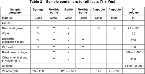
Metal or plastic containers may be preferred where adequate protection of glass containers is not available for the transportation of oil samples.
For dissolved gas analysis (DGA), to minimize losses of the low solubility gases (H2 and CO) and pick-up of air at low total gas contents, it is critical to strictly follow the sampling procedures of 4.2.2 to 4.2.5, particularly with bottles and ampoules. Also only the materials recommended for caps, gaskets, valves and tubing of sample containers should be used by well-trained and experienced personnel familiar with those containers.
When using bottles for DGA, water and breakdown voltage, care should be taken to minimize air contact with the oil sample during sampling and analysis.
The use of plastic bottles is not permitted for DGA, water and dielectric strength, since ambient air contamination and gas losses may occur by diffusion through the plastic. For the other tests, plastic bottles should be made of a compatible plastic (such as high-density polyethylene (HDPE), polypropylene or polycarbonate), which does not contaminate the oil with additives contained in the plastic. Each new type of plastic (and glass) bottle should be tested for compatibility with oil.
The recommendations of 4.2.1 .3 and 4.2.1 .6 (cleaning of sampling point and sampling equipment) should be followed strictly for water content, dielectric strength, dielectric dissipation factor, interfacial tension and particles content.
The other physical and chemical tests (viscosity, density, acidity, DBPC, furans and PCB contents, etc.) are less affected by the sample containers and sampling procedures used.
4.2.1.6 Cleaning of sampling equipment
4.2.1.6.1 Use of disposable sample containers
Use of disposable, pre-cleaned metal, plastic and glass bottles having a known level of cleanliness for dust and humidity has been found by several users more convenient than cleaning them. Such sampling devices are relatively inexpensive and available from several vendors of labware or veterinarian equipment. To verify that the cleanliness of disposable bottles is acceptable, a few un-cleaned and cleaned bottles can be tested in parallel.
4.2.1.6.2 Cleaning procedures
Non-disposable sampling devices may be cleaned in a dishwasher using a detergent, and rinsed with tap water (without detergent in the rinse aid compartment of the dishwasher). A last, optional rinse with de-ionized water may be used.
Sampling equipment and containers may also be cleaned with normal heptane.
After cleaning, the sampling devices are dried in an oven at typically 100 °C until fully dried, then allowed to cool in the oven or a dry box.
After drying, they shall be immediately closed to protect from contamination and not opened until just before use.
Appropriate cleaning of sample containers is critical for DDF and interfacial tension, which are particularly sensitive to contamination. They should not be cleaned with solvents.
Dedicated sampling containers cleaned according to IEC 60970 are recommended for measuring particles content in oil.
4.2.2 Sampling of oil by syringe
4.2.2.1 Sampling equipment
The following sample equipment shall be used:
a) Graduated gas-tight syringes of a size suitable for containing adequate oil sample volume (20 ml to 250 ml), and equipped preferably with a three-way plastic valve made of nylon body and polypropylene (PP) barrel, or with a three-way stainless steel valve. The use of syringes with matched piston and barrel is preferred when sampling for DGA in order to allow the piston to flow freely with oil volume variations, and to avoid pressure and vacuum build-up in the syringe and breakage during handling. Plastic syringes should not be used.
For plastic three-way valves, a new valve should be used each time an oil sample is taken and not recycled, because it may be contaminated with the previous oil sample and lose its gas tightness when used several times. For added protection during transportation, a stainless steel Luer-Lock cap may be placed on top of the 3-way valve. This cap may be recycled after use.
NOTE Priming the piston with clean, degassed oil has been found useful to avoid the formation of bubbles along the piston when introducing the oil sample for DGA analysis. The use of a low viscosity water-soluble lubricant has also been found useful for DGA.
The size of sample required depends on the likely concentration of gas in the sample, the analytical techniques and the sensitivity required. For DGA after factory tests, a 250 ml syringe has been found convenient.
b) Transport containers, designed to hold the syringe firmly in place during transport but which allow the syringe plunger freedom to move and prevent its tip from contacting the container whatever its position during transportation. Cardboard boxes with removable inner cardboard flaps that hold the barrel in place have been found convenient for that purpose. Metal or plastic cylinders with inside foam packing have also been found appropriate for transportation. When sampling for DGA, the syringe should preferably be transported in the vertical position, piston upwards, to avoid the formation of bubbles in oil.
4.2.2.2 Sampling procedure
See Figure 5.
a) The electrical equipment is connected as shown in Figure 5a, and its sampling valve (5) opened.
b) The three-way valve (4) is adjusted (position A) to allow 1 l to 2 l of oil to flow to waste (7).
c) The three-way valve (4) is then turned (position B) to allow oil to enter the syringe slowly (Figure 5b). The plunger should not be withdrawn but allowed to move back under the pressure of the oil.
d) The three-way valve (4) is then turned (position C) to allow the oil in the syringe to flow to waste (7) and the plunger pushed to empty the syringe. To ensure that all air is expelled from the syringe, it should be approximately vertical, nozzle upwards, as shown in Figure 5c. Confirm that the inner surfaces of the syringe and plunger are completely oiled.
e) The procedure described in steps c) and d) is then repeated until no gas bubble is present. Then the three-way valve (4) is turned to position B and the syringe filled with oil (Figure 5d).
f) The three-way valve (2) on the syringe and the sampling valve (5) are then closed.
g) The three-way valve (4) is turned to position C and the syringe disconnected (Figure 5).
h) When sampling for DGA, if the oil taken from the electrical equipment is hot, place the syringe in its protective box in the vertical position, standing on the piston and with the syringe tip upwards, until the oil has slowly cooled down, then install the syringe back into the holding flaps of the protective box for transportation. This will prevent the formation of bubbles in oil.
Label carefully the sample (see 4.4).
NOTE 1 It is good practice to avoid contamination of the outer surface of the plunger and inner surfaces of the syringe by dust or sand. Such particles can affect the sealing properties of the syringe. This kind of contamination can come from wind-swept dust or from the handling of the syringe.
NOTE 2 In the case of sealed transformers, if a bubble appears in the syringe directly after sampling, it is recommended to resample.
4.2.3 Sampling of oil by ampoule
4.2.3.1 Sampling equipment
The following sample equipment shall be used:
a) Glass or metal ampoule, typically of volume 125 ml to 1 l. It may be closed either by stopcocks or pinchcocks on oil-compatible plastic tubing or by valves. Glass ampoules are usually made of Pyrex glass. Metal ampoules are made of stainless steel and may use spring-loaded valves instead of plastic tubing as expansion devices.
The oil-compatible plastic tubing used for ampoules should be used only once, not recycled, since it has a memory effect and may contaminate the oil sample when sampling for DGA. The types of compatible plastic tubing are indicated in 4.2.1.4.
A sampling tube and its seal design is acceptable if the loss of hydrogen of the sample contained is less than 2,5 % each week.
The size of sample required depends on the tests to be carried out and, for DGA, the likely concentration of gas in the sample, the analytical technique and the sensitivity required. For DGA after factory tests, a 250 ml ampoule has been found convenient.
b) Transport containers, designed to hold the sampling tubes firmly in place during transport.
4.2.3.2 Sampling procedure
See Figure 6.
a) The device is connected as shown in Figure 6.
b) The cocks (2) on the plastic tubing of sampling ampoule (28) and the equipment sampling valve (5) are carefully opened so that oil flows through the sampling ampoule to waste (7). When sampling for DGA, oil should flow under a non-turbulent flow (until there are no air bubbles in the oil), to avoid the formation of bubbles in oil and the stripping of dissolved gases out of oil.
c) After the sampling ampoule (28) has been completely filled with oil, about 1 l to 2 l are allowed to flow to waste (7).
d) The oil flow is then closed by shutting off firstly the outer cock (2), then the inner one (2) and finally the sampling valve (5).
e) The sampling tube (28) is then disconnected and the sample carefully labelled (see 4.4).
NOTE If a glass sampling ampoule with integral glass cocks is used, it is preferable to drain 1 ml or 2 ml of oil from it prior to transporting it back to the laboratory in order to avoid breaking the ampoule in the event of it being exposed to a rise in ambient temperature. Record on the label that this has been done.
4.2.4 Sampling of oil by flexible metal bottles
4.2.4.1 Sampling equipment
The following sample equipment shall be used:
a) Flexible metal bottles capable of being sealed gas-tight, typically of volume 250 ml to 2,5 l.
Metal bottles should not be soldered, as materials used for soldering may contaminate the oil. Adsorption on aluminium surfaces of water contained in oil is possible. Metal bottles made of drawn aluminium or of welded tin are flexible and do not need oil expansion devices. They should be filled completely with oil by pressing on the bottle sides before closing the bottle.
Metal bottles should be closed with a screw cap lined with a non-porous, leak-free gasket compatible with oil. Gaskets should be used only once, not recycled, except if they are lined with aluminium foil on the oil side.
For DGA and water analysis, the porosity of gaskets used should be measured by taking at least 6 samples of oil from a transformer into identical bottles. The hydrogen content of the oil used for testing of the sampling equipment should be at least 100 µl/l. Analyse samples for hydrogen content at intervals over a month, the first being as soon as possible after taking the samples. A bottle and seal design is acceptable if it permits losses of hydrogen of less than 2,5 % per week. Suitable bottles have, for example, screwed plastic caps holding a conical polyethylene (PE) seal or flexible gasket (see Figure 7).
For analytical tests other than DGA and water, the above requirement for gas tightness does not apply.
For mineral oils, gaskets should be made of polyethylene (PE), PTFE or nitrile-butadiene rubber (NBR) (containing more than 30 % of nitrile component).
For non mineral oils (e.g. natural and synthetic esters), gaskets should be made of PTFE (not NBR or silicone rubber).
b) Transport containers, designed to protect the bottle during transport.
4.2.4.2 Sampling procedure
See Figure 7a.
a) The sampling valve (5) is carefully opened and about 1 l to 2 l of oil allowed to flow under a laminar flow to waste (7) through the tubing (3) ensuring that all gas bubbles are eliminated before the oil sample is collected and gases are not stripped out of the oil by the oil flow.
b) Place the end of the tubing (3), with the oil still flowing, at the bottom of the sampling bottle and allow the bottle to fill from bottom up. Rinse the bottle with one-third of oil then send the oil to waste.
When sampling for DGA, introduce the oil under a continuous, non-turbulent flow, until no gas bubbles are observed in oil when it flows out of the bottle in order to avoid the formation of bubbles in oil and the stripping of dissolved gases out of oil (otherwise significant gas loss may occur). Filling the bottle should be slow enough to allow laminar flow of oil and as fast as possible to avoid gas loss to (and contamination from) the atmosphere. If the time to fill the bottle exceeds a few minutes, a new sample should be taken.
When sampling for water, strictly follow the recommendations of 4.2.1.3.
c) Allow about two bottle volumes to overflow to waste (7), then withdraw the tubing (3) slowly with the oil still flowing. Gently squeeze the sides of the bottle so it is entirely filled with oil, then securely close with the cap.
d) Close the sampling valve (5) and disconnect the tubing. Label the sample (see 4.4). Tighten the cap again after the oil has cooled to ambient temperature.
4.2.5 Sampling of oil by glass and rigid metal bottles
4.2.5.1 Sampling equipment
The following sample equipment shall be used:
a) Glass or rigid metal bottles capable of being sealed gas-tight, typically of volume 125 ml to 2,5 l. Clear glass bottles shall be protected from sunlight, so the use of dark bottles is highly recommended. Even so, for samples for DGA, extra protection from light should be provided during transport and storage.
Caps and gaskets described for flexible metal bottles in 4.2.4.1 are suitable for glass and rigid metal bottles.
b) Transport containers, designed to protect the bottle during transportation.
4.2.5.2 Sampling procedure
See Figure 7a.
Sampling procedures are the same as for flexible metal bottles in 4.2.4.2, except that glass and rigid metal bottles should not be filled entirely with oil.
Instead, allow the oil level to fall a few centimetres from the rim so as to leave a small expansion volume of air (typically, 3,5 ml to 7 ml, or 1,5 cm to 3 cm of airspace), to allow for oil expansion with increasing temperatures. Fill with no less than 90 % of oil to allow for air expansion when temperatures decrease and avoid implosion of the glass bottle. Place the bottle cap securely in position and label the sample (see 4.4). Indicate the approximate expansion volume of air on the label. Correction for gas loss to the small headspace volume of air in the bottle will be calculated by the laboratory as indicated in Annex D of IEC 60567:2011.
Where transport and storage conditions are not particularly demanding, some companies prefer to have the bottles filled completely and closed lightly, finger-tight, with a screwed plastic cap having a conical polyethylene seal. In the event of expansion of the oil by heat, these caps act as a non-return valve, allowing a small amount of oil to escape. Where contraction by cooling occurs, the seal will prevent ingress of air. In the latter case, the bottle will need to be warmed up to the sampling temperature to re-dissolve the gases prior to analysing for dissolved gases.
For other analytical tests, an air space can be left above the oil.
4.2.6 Sampling of oil by plastic bottles
4.2.6.1 Sampling equipment
The following sample equipment shall be used:
Plastic bottles should be made of a compatible plastic (see 4.2.1.5), which does not contaminate the oil with additives contained in the plastic. Each new type of plastic bottle should be tested for compatibility with oil. Use of virgin plastic without fillers or pigments is strongly recommended.
Plastic bottles should not be used for DGA, water content and dielectric breakdown.
Caps and gaskets described for metal bottles in 4.2.4.1 are suitable for plastic bottles.
Moulded all-plastic caps, of suitable composition as above, are suitable.
4.2.6.2 Sampling procedure
See Figure 7a.
Sampling procedures are the same as for flexible metal bottles in 4.2.4.2.
4.3 Storage and transportation of samples
Some of the dissolved oxygen present in the oil sample may be consumed, and hydrocarbons and carbon oxides formed by oxidation. This reaction is accelerated by exposure to light, therefore sampling devices made of transparent materials (syringes, glass bottles and ampoules) should be protected (for example, by wrapping them in an opaque material or placing them in a box for transportation).
In any case, the analysis should be carried out as soon as possible after sampling to avoid oxidation reactions and gas losses or pick-ups from the sampling devices.
Oil syringes (and other oil sampling devices) may be placed in sealed boxes to fully eliminate the risk of formation of bubbles in important DGA oil samples during transportation in planes, due to reduced pressure and over-saturation of gases in the oil. The syringe plunger should be allowed to move in order to prevent air ingress in case of oil volume variations.
4.4 Labelling of samples
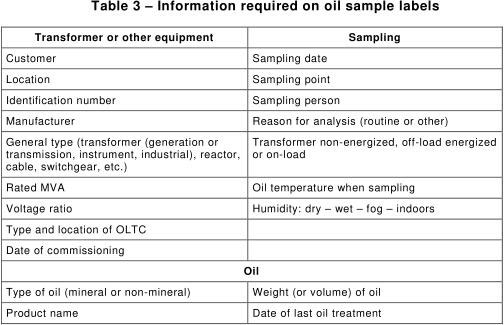
Oil samples should be properly labelled before dispatch to the laboratory.
The following information, as shown in Table 3, is necessary (whenever it is known).
The following additional information is desirable:
- ambient temperature, reading of winding temperature indicator, reading of MVA or load current or percentage load, operation of pumps, mode of communication of its tap-changer with the main tank, oil preservation system (conservator, nitrogen blanket, etc.) and any changes in operational conditions or any maintenance carried out since last sampling;
- for water in oil analysis, temperature of oil, the method used for measuring the temperature, and whether or not the fans and pumps are running (to be able to calculate the relative humidity of oil);
- time of sampling where more than one sample is taken.