

IEC 60567 OIL-FILLED ELECTRICAL EQUIPMENT - SAMPLING OF GASES AND OF OIL FOR ANALYSIS OF FREE AND DISSOLVED GASES - GUIDANCE
7 Extraction of gases from oil
7.1 General remarks
Removal of dissolved gases from oil for analysis may be accomplished either by vacuum extraction, stripping or head space.
The multi-cycle vacuum extraction (Toepler) method is described in 7.2.
The single-cycle vacuum extraction (partial degassing) method is described in 7.3.
The stripping method is described in 7.4.
The head space method is described in 7.5.
7.2 Multi-cycle vacuum extraction using Toepler pump apparatus
In this method, an operating procedure which attempts to remove as much as possible of the dissolved gas from the oil is used. It is normally possible to remove about 97 % of the more soluble gases and even higher percentages of the less soluble gases. Such a small imperfection is rarely significant when considering overall accuracies, but, in any case, the preferred method of calibration using gas-in-oil standards takes account of incomplete extraction.
NOTE To calibrate this method with gas-in-oil standards, the procedure described in 6.1 for preparation of argon-free standards should be used, since the calculation will be affected by the amount of dissolved argon that will be extracted but not detected by the gas chromatograph.
7.2.1 Toepler pump extraction apparatus
An example of a suitable design is shown in Figure 9a. Note that Figure 9b includes recommended volumes. In this design, oil containing gas in solution is injected through a septum (9). Alternatively, after the equipment has been evacuated, oil may be withdrawn from an oil sample bottle via a tube attached to valve (V8) which has previously been filled with oil (see Figure 9c).
The Toepler pump extraction apparatus shall
a) be capable of subjecting the liquid to a vacuum less than 10 Pa;
b) be vacuum-tight. The vacuum tightness of the whole system may be verified by carrying out the extraction procedure but without introducing oil, as follows.
Carry out steps b), c) and d) of 7.2.2. Omit step e). Continue with steps f), g) and h) as if oil were present. After compression of gas to atmospheric pressure in step h), the amount of gas should be less than 0,1 ml;
c) permit the measurement of extracted gas to be made to the nearest 0,05 ml or better, at normal temperature and pressure.
In addition:
d) all tubing connecting the degassing flask (3) to the gas collection flask (2) (in Figure 9a) shall be of large bore, at least 5 mm internal diameter and as short as practicable;
e) the vacuum gauge used cannot be of a type that operates at high temperature or uses ionizing radiation (thermocouple, ionization or Penning gauges) since these can produce gases of the types being measured by cracking the oil vapours present in the system. Since it may react with extracted gases, a Pirani gauge is not suitable either. A sensor based on capacitance changes between two chambers is suitable. It is recommended that two sensors be used, one in the vacuum chamber, the second for measuring gas volumes at atmospheric pressure.
Further requirements are noted in 7.3 in which the partial degassing method is described.
Since the detailed design of this apparatus is not standardized, it is necessary to establish an operation which will ensure adequate extraction of all components of the dissolved gas. The main parameters that need to be established are the number of degassing cycles (strokes) of the Toepler pump that should be used and the time for which each degassing cycle should last. This operation is preferably established by degassing a gas-in-oil standard as follows.
Use the extraction procedure as detailed in 7.2.2 but, instead of degassing an unknown oil sample, substitute a gas-in-oil standard of the volume normally used containing all the gases listed in 8.1.
Degas successive standards until a number of cycles of the Toepler pump, together with a degassing time on each stroke, has been established so that the area or height of each peak on the chromatogram of the extracted gases is within 95 % of the area or height of that peak on the chromatogram of the same quantities of gases injected directly into the chromatograph by means of a standard gas mixture (see 8.6). A degassing time on each cycle of 1 min to 3 min is frequently used; the shorter the time the more degassing cycles are likely to be required.
The above procedure serves to establish a routine of operation, which will apply until any major changes are made to the equipment and will also apply to other equipment of the same design. It is recommended that the overall calibration of the complete equipment (degassing equipment plus chromatograph) is checked periodically (for example, every six months) using gas-in-oil standards to provide correction factors to be applied to areas or heights of chromatogram peaks.
7.2.2 Extraction procedure
The following is a typical extraction procedure used when a sample is in a syringe. It is described by reference to the apparatus shown in Figures 9a and 9b, the circled numbers refer to those figures. Modifications in the procedure may be needed for apparatus of other designs.
a) Weigh the syringe (5) containing the oil sample and connect it to the degassing flask (3). When a bottle is used as a container (Figure 9c), the mass of oil degassed is determined by weighing the degassing flask before and after introducing the oil.
b) Open valves V1, V2, V4, V6, V7 and V9. Close valves V3, V5 and V8. The valve V13 is a solenoid-operated three-way valve which at this stage is not energized and connects the vacuum pump VP1 to the system.
c) Switch on the vacuum pumps VP1 and VP2 and the magnetic stirrer (8).
d) When the pressure has fallen to 10 Pa, close valves V2, V6 and V7.
e) Open valve V8 and inject a sufficient oil sample through the septum (9) into the degassing flask (3). This is the start of the degassing part of the Toepler pump cycle.
NOTE 1 A gas bubble in the syringe suggests that the plunger has stuck and indicates the desirability of a new sample. If this cannot be provided, ensure that the bubble is introduced together with all of the oil or is re-dissolved in the oil by shakinq the syringe.
NOTE 2 The minimum oil volume to be used is the volume necessary to produce enough gas volume for injection in the gas chromatograph. When this is possible, larger oil volumes may be used to increase the precision of the analysis. For oil from a factory test, a modification may be needed; see note 3 of step j) below.
f) After the established degassing time (for example, 1 min to 3 min) continue the first Toepler pump cycle by switching valve V13 so as to admit low-pressure compressed air above the mercury which rises to the level of contact (a), compressing gas from the collection flask into the burette. Reversal of valve V13 to connect the vacuum pump to the mercury reservoir (1) allows the mercury to return (the gas collected in the burette being trapped by the non-return float valve V10) and further gas to be extracted from the oil. The contacts allow this cycle to be automated. Inductive level switches may be used instead.
An electric counter is helpful in counting the number of cycles and for stopping the procedure after the required number of cycles, as established as standard for the apparatus. Alternatively, the equipment may be run automatically for a standard time (for example, 10 min for a cycle time of 1 min).
The number of strokes should be such that the vacuum at the end of extraction approaches the initial value before extraction. The number of strokes necessary depends on the ratio between the total volume of the equipment and the volume of the pump. Typically, 4 to 20 strokes have been found suitable to reach 97 % extraction for the more soluble gases, depending on the equipment used.
g) Switch off the automatic cycling control (if used) and set valve V13 to admit air. Allow mercury to rise into the burette to above the level of valve (V5). Close valve (V4).
h) Open valve (V6) and adjust the mercury levelling vessel (7) to bring the mercury surfaces to the same level. Read the total volume of gas collected in the burette. Note the ambient temperature and pressure.
i) Remove and reweigh the oil syringe to obtain the mass of oil that has been degassed. Determine the density of the oil at ambient temperature.
j) Close valve (V1), open valve (V2) to admit the extracted gas into the sample loop. Again adjust the mercury levelling vessel to bring both the mercury surfaces to the new level and close valve.
NOTE 1 Another arrangement frequently used is to fit a septum on the top of the burette in place of valve (V2) and to transfer an aliquot of gas to the chromatograph by means of a precision gas-tight syringe. In such a case, it is good practice to fit a new septum each time the equipment is used.
NOTE 2 If an inadequate quantity of gas has resulted from degassinq the first oil sample, the degassing flask may be disconnected and emptied, and the method repeated with a new oil sample. The first quantity of extracted gas is retained in the burette by keeping valve (V4) closed until the remainder of the system is re-evacuated (step d) above).
Alternatively, where concentrations of gas are expected to be low, a larger degassing flask, up to 2 l, may be fitted, with sample volumes up to 500 ml. Introduce the oil sample slowly to facilitate gas extraction.
k) Calculate the total gas content extracted CT of the oil sample in ul/l at 20 °C and 101,3 kPa from the expression:

where
P is the ambient air pressure, in kPa;
t is the ambient air temperature, in °C;
V is the total volume of gas extracted, at ambient temperature and pressure, in ml;
d is the density of oil corrected to 20 °C, in g/ml;
m is the mass of oil degassed, in g
l) Carry out the analysis as in Clause 8.
NOTE Because the gas is not totally extracted from the oil, a rinse step may be required after a high concentration has been run (for example, after analysis of oil sample from tap changer). The extractor can be rinsed with oil containing non-detectable quantities of gases, except for those present in the air.
7.3 Vacuum extraction by partial degassing method
In this method, gas extraction is accomplished by only one exposure to vacuum. Extraction efficiency depends on component gas solubility. Correction of this incomplete gas extraction can be obtained by calculation from the Ostwald solubility coefficients of the gases in transformer oil (see Annex B).
7.3.1 Partial degassing apparatus
Equipment such as that shown in Figures 9a and 9b is equally suitable for this method with the following changes.
a) The automatic control arrangements used in the Toepler pump mode (valves V10 and electric contacts a, b and c are not required. A simple hand pump (blow-ball) can be fitted in place of the low-pressure compressed air supply.
b) The total expansion volume (degassing flask (3) plus collection flask (2) and connecting tubing, less the oil volume) should be at least 20 times the oil volume. In the apparatus shown in Figure 9b, a collection flask of 500 ml and a degassing flask of 150 ml are suitable for an oil volume of 25 ml to 30 ml.
c) The mercury reservoir volume should not greatly exceed that of the collection flask; in the apparatus shown in Figure 9b, a reservoir volume of approximately 600 ml to 700 ml is recommended. The reservoir should be filled with mercury to leave an air space of not more than 100 ml to 150 ml.
d) A mark should be made on the dip tube in the mercury reservoir, (mark d in Figures 9a and 9b) so that when the equipment is used for partial degassing the mercury can be brought to this mark and the expansion volume thus accurately defined.
e) The apparatus shall be leak-free and capable of evacuation to 0,1 Pa. The burette, typically 3,5 ml, shall be calibrated in 0,01 ml divisions, and the connecting tubing and vacuum gauge as in points d) and f) of 7.2.1.
f) Alternatively to the syringe, the needle and the septum, a flexible PTFE tubing connected to the valve can be used to introduce oil samples.
7.3.2 Extraction procedure
a) Weigh the syringe (5) containing the oil sample and connect it to the degassing flask (3).
b) Proceed as in steps b) to e) of 7.2.2, evacuating down to 0,1 Pa.
c) Allow degassing to continue for 5 min to 10 min, depending on the oil viscosity, with the stirrer operating vigorously. Then close valve (V9).
d) Proceed as in steps g) and h) of 7.2.2.
e) Calculate the total gas volume extracted by dividing the volume of gas collected in the burette by the volumetric collection ratio Vc/Vt , where
Vc (collection volume) is the volume of the burette and collection flask (2), from mark "d" to valves V9, V6, V5 and V2;
Vt (total expansion volume) is Vc plus the volume of the degassing flask (3) and connecting tubing to V9, V8 and V7, less the volume of oil.
f) Remove and reweigh the syringe to obtain the mass of oil that has been degassed. Determine the density of the oil at ambient temperature.
g) Correct the calculated total volume of gas extracted to 20 °C and 101,3 kPa as in step k) of 7.2.2.
h) Inject an aliquot of the gas extracted into the chromatograph as in step j) of 7.2.2.
i) Carry out the analysis as in Clause 8.
j) Calculate the actual concentration of each gas component originally present in the oil sample, by dividing its chromatographically measured concentration by its extraction efficiency Ei (see Annex B).
NOTE Because the gas is not totally extracted from the oil, a rinse step may be required after a high concentration has been run (for example, after analysis of oil sample from tap changer). The extractor can be rinsed with oil containing non-detectable quantities of gases, except for those present in the air.
7.4 Stripping extraction method
The extraction of dissolved gases is carried out by the carrier gas itself bubbling through a small volume of the oil. Typically an oil volume between 0,25 ml and 5 ml is used.
The time required to extract larger volumes would give unacceptable gas chromatograms except when used with cold traps or for hydrogen analysis only.
7.4.1 Stripping apparatus
Various designs of strippers are used. Figure 10 shows borosilicate glass strippers. Oil is injected into the stripper from a syringe via a rubber septum. This septum can be used several times (3 to 10 depending on the size of the needles) before leakage occurs.
A design of a stripper made of stainless steel is shown in Figure 11. A needle with a cock and interchangeable syringe connection is permanently fixed into the base of the stripper and a syringe containing oil is attached to the fixed needle. The oil is injected by the movement of a pneumatic actuator on the syringe plunger.
The volume of oil injected shall be measured with an accuracy better than 1,0 %. Injection from a precision syringe has been found to achieve this requirement but difference of syringe mass before and after injection is to be preferred if better accuracy is required.
7.4.2 Outline of procedure
a) As shown in Figure 12a connect the stripper in place of the sample loop of the gas chromatograph gas sampling valve preferably using compression fittings. Vacuum rubber tubing may alternatively be used for the connections then verify that there is no leakage due to overpressure of the carrier gas; if such is the case, reduce the overpressure.
b) Maintain the stripper at a controlled temperature between 20 °C and 80 °C. Indeed, elevated temperatures reduce oil viscosity and facilitate gas stripping.
c) Allow the carrier gas to flow through the stripper.
d) Before injection of the oil check that the operating conditions of the equipment are satisfactory and particularly that the baseline on the recorder is stable.
e) Inject the oil to be analysed into the stripper. The volume of oil to be injected will depend upon the type of stripper used and the expected gas content. During this operation the carrier gas flow through the stripper shall be maintained.
f) After the analysis has been completed some stripper designs permit a back-flush of the injected oil to waste without disconnecting the stripper. If the stripper is to be disconnected for cleaning, the gas outlet tube should be disconnected first to avoid the possibility of the oil sample entering the gas sampling valve. Carry out the analysis as in Clause 8.
7.5 Head-space method
7.5.1 Principle of the method
In this method a volume of oil V L is introduced in a glass vial in contact with a gas phase ("head space") of volume VG. A portion of the gases dissolved in the oil (H2, O2, N2, CH4, C2H2, C2H4, C2H6, CO and CO2) transfers to the head space, under equilibrium conditions of temperature, pressure and agitation. The head space is transferred to an injection loop or directly in the column of the gas chromatograph depending on the apparatus used. Calibration curves are used to establish the concentration of each gas in the head space. The concentrations of the gases in oil are then calculated by using Henry's law and experimentally determining the partition coefficients of the oil or by direct calibration with gas-in-oil standards. A schematic representation of this method is shown in Figure 13.
Warning : This method will provide reproducible results only if all the operation and calibration parameters are precisely controlled, otherwise significant errors may occur. The following parameters are of particular importance: total volume of vials, volume of oil, tightness of septa, temperature, dilution with argon and actual pressure in the vials after each step of the procedure. The same exact parameters should always be used for field samples, gas standards, and oil standards. Operation and quality control by highly skilled personnel is recommended.
7.5.2 Symbols and abbreviations
V total volume of the vial
VG volume of the gas phase in the vial
VL volume of the oil phase in the vial
CG concentration of gas (i) in the gas phase of vial, obtained by GC (gas chromatography)
concentration of gas (i) in the oil sample, obtained directly from CG using calibration curves with gas-in-oil standards
P, t atmospheric pressure and temperature when the oil sample was analyzed, (P in kPa; t in °C)
Ps, ts atmospheric pressure and temperature when the gas-in-oil standard, or the gas standard, was analyzed (P s in kPa; t s in °C)
K partition coefficient of gas (i), for the calculation of CL using gas standards
concentration of gas (i) in the oil sample
7.5.3 Head-space extraction apparatus
An example of a suitable design includes the following components.
7.5.3.1 Head-space sampler
This sampler is equipped with a transfer line connected directly or through a T union to the first column of the gas chromatograph. Samplers equipped with syringe injection have not been evaluated.
NOTE The size of injection loops should be adapted to the type of columns in order to avoid broadening of peaks. If injection loops larger than 1 ml are used, it should be verified that the overpressure is high enough to adequately flush the sample loop and fill it to atmospheric pressure prior to the injection step (this will depend on the volume of the circuit between the vial and the vent in some systems).
A second injection loop may be necessary for injecting gas mixtures directly into the chromatograph, to check the response of the GC detectors daily with calibrated gas, and to perform Buchholz analysis. These operations are also possible using the head-space sampler, after transferring the calibrated gas mixture or the Buchholz gas sample into pre-purged vials.
7.5.3.2 Head-space glass vials
Use head-space vials suitable for use with the equipment. The actual volume of commercial vials may differ from the nominal value.
NOTE 20 ml vials have shown good performance. Their actual volume is closer to 22,3 ml.
The total volume of the vial V has a great influence on the value of the VG/VL ratio, and on the final results. Since significant variations of volume can occur between different batches of vials and between different vials of the same batch, the average value for each batch of vials purchased by the laboratory should be determined when they have different batch numbers. This can be done by measurement of the mass of pure water that can be contained in a vial according to the procedure described below in 7.5.3.2.1.
Condition 10 to 20 vials from the same batch and 100 ml of distilled water for 1 h at room temperature and note the temperature.
7.5.3.2.1 Head-space glass vials calibration procedure
Determine the weight of the empty vials to the nearest 0,01 g. Fill the vials completely with
distilled water as shown in Figure 14 and reweigh to the nearest 0,01 g. Calculate the volume
of each vial by using the following equation:
V = (W - Wo)/D
where
V is the total volume of the vial, in ml;
Wo is the weight of the empty vial, in g;
W is the weight of the vial filled with water, in g;
D is the density of water at measurement temperature, in g/ml.
Calculate the mean volume and the relative standard deviation s % for the vials tested. If the value of s % is higher than 1 %, the controlled batch of vials is rejected and a new batch of vials shall be tested.
7.5.3.3 Rubber septa
The brands of septa used should not introduce contamination of the vials during analysis and should not leak after having been punctured by needles, especially by the large diameter needles in 7.5.4.1.2.
The suitability of septa is checked by analysis on blank vials containing argon only at atmospheric pressure, having been punctured the same number of times as the vials containing the oil samples or gas standards and left 24 h at room temperature. Very low quantities of oxygen and nitrogen should be found (not more than 150 ul/l O2 and 350 ul/l N2).
Another means of checking septa is by immersing the closed vial with its pierced septum in a water bath heated at 90 °C and check for bubbles This test is useful also for checking the crimping method.
NOTE 1 Only PTFE-lined septa should be used, preferably of the chlorobutyl rubber, high-temperature type (PTFE = polytetrafluoroethylene =Teflon(R)). White and red rubber septa have been found to leak and should be avoided. Blue ones have been found acceptable. In any case, new types of septa should be checked before use. The quality of the crimping equipment (crimping head and perforated aluminium caps) and the skill of the operator have been reported as critical.
NOTE 2 When the reliability of septa cannot be assessed with certainty, it is recommended that subprocedure 7.5.4.1.1 (preparation of vials in an inert box) be used.
7.5.3.4 Oil syringes
Appropriate oil volumes, measured as precisely as possible, are introduced in the vials, so that the VG/VL ratio is the same for all field samples and gas-in-oil standards analysed. Volumes of 10 ml to 15 ml have been found suitable, but lower or larger oil volumes may be used depending on the gas content of the oil sample. Glass syringes of 20 ml, 30 ml or 50 ml can be used. New batches of syringes should be calibrated with the following procedure.
Fill a syringe with 20 ml of oil of known density. Weigh the filled syringe to the nearest 0,01 g. Draw 15 ml of oil from the syringe then reweigh the syringe. Subtract the two weights to obtain the weight of oil drawn. Calculate the volume of oil by dividing the weight of oil by the density of the oil. Perform this test on 20 syringes of each new batch. Calculate the standard deviation(s) and s % for the 20 syringes. If s % is higher than 1,3 %, the controlled batch of syringes is rejected and a new batch of syringes shall be tested.
Glass syringes are not intended for precise volumetric work The index mark on the piston is about 1/2 ml in width, allowing considerable variations with operators. Therefore, the exact amount of oil introduced in a vial should be measured by weighing the vial or the syringe before and after introduction of the oil (see 7.5.4.1).
Two different types of needles are needed (A and B). For type A, 0,84 mm ID (gauge 18) (for the transfer of oil) and for type B, 0,25 mm ID (gauge 26) (for the transfer of gases and pressure equilibration) have been found suitable. Needle size should be adapted to the type of septa to ensure that they will not induce leaks (see 7.5.3.3).
For procedure of 7.5.4.1.2, a maximum size of 0,84 mm ID and 1.27 mm OD (gauge 18) is recommended to avoid leaks through the septa.
For procedure of 7.5.4.1.1, larger size needles may be used as they will not be used to pierce septa, and a larger size needle will facilitate oil introduction.
7.5.3.5 Inert boxes
An inert box (either a glove box, a glove bag or a "revolving table") is required for the procedure of 7.5.4.1.1.
7.5.3.5.1 Glove box
The glove box and its lock chamber should be purged with at least 5 times its volume of argon (typically, at 400 ml/min). Alternatively, a plastic glove bag, filled with all the necessary equipment (syringes, vials, etc), then purged with argon, may be used.
7.5.3.5.2 Revolving table
The "revolving table" is described in Figure 15: a carousel carrying 20 empty vials is placed in a circular housing hermetically covered by a transparent removable lid. The carrousel can be rotated from outside with a knob.
A septum is attached to one side of the lid, and a vial crimper on the other side, both facing the mouth of the vials.
The revolving table is continuously flushed with inert gas (the same used as carrier gas) at a known and constant flow rate and pressure, to ensure constant operation conditions.
7.5.3.6 Head-space operational conditions
See Table 1.
 Monitoring/recording of measurable parameters (argon overpressure, temperature, etc.) within a precision of +/-0,5 % is advisable to verify if they have not changed accidentally during an extended run.
This can be done by recording or printing the electronic reading of pressure available within the head-space equipment during the analysis. This may need important modifications for some head-space samplers that have only mechanical reading of the pressure.
Atmospheric pressure and ambient temperature shall be recorded when filling the vials, within a precision of +/-0,5 %, to be able to calculate actual quantities of gases introduced at the various steps of the procedure, and/or to convert to the conditions of this standard.
7.5.3.7 Gases
Argon used shall be chromatography graded (typically, >99,999 % pure).
Standard gas mixtures supplied with a calibration certificate of +/-1 %, if available, or at least +/-2 %, are used to establish a calibration curve for each dissolved gas. The concentrations of the mixtures should be chosen in order to fully cover the expected concentration range of field samples, which depends on the type of equipment to be monitored.
Different levels of concentrations in the calibration curve may be obtained by injecting different volumes of the same standard mixture or by using different standard mixtures in a suitable concentration range.
7.5.4 Head-space extraction procedure
7.5.4.1 Preparation of vials
Two alternate methods are possible, using either an inert box or needles.
7.5.4.1.1 Preparation of vials in an inert box
This method has the advantage that septa are never punctured before being placed in the headspace carrousel. The risk of septa leak (with its dramatic effect on analysis results) is therefore much reduced.
7.5.4.1.1.1 Pre-purging of vials
Pre-purging can be carried out
a) in the glove box: for practical reasons, series of 10 samples are prepared. Label and weigh 10 vials with their corresponding perforated aluminium caps and septa (uncrimped) to the nearest 0,01 g. Place the 10 weighed vials, 10 glass syringes of 20 ml, and 10 oil samples in their glass syringes or glass ampoules in the lock chamber of the glove box. Purge the lock chamber with argon. Transfer the content of the lock chamber into the glove box filled with argon.
b) in the revolving table: up to 20 empty vials weighted as above and their corresponding caps and septa (of known average weight) are placed in the closed housing. Purge with argon for 10 min to 15 min.
7.5.4.1.1.2 Preparing vials with oil samples
Vials with oil samples can be prepared as follows:
a) in the glove box: with a 3-way valve transfer about 5 ml of the first oil sample into a glass syringe and rinse the entire body of the syringe with the oil. Release the 5 ml oil to waste and fill the glass syringe with 20 ml of oil. Disconnect the oil syringe or glass ampoule and fix a needle to the glass syringe.
Release about 5ml of oil to waste, then fill an empty vial with the remaining 15 ml of oil with the tip of the needle to the bottom of the vial. Adjust the volumes if a lower final oil volume (between 10 ml and 15 ml) has been chosen.
Close the vial with its septum and crimping cap and crimp with the help of the crimping bead, making sure that the lined side is turned towards the inside of the vial.
NOTE Closing the vial should be done within 45 s after the vial has been filled with oil; otherwise, the sample should be discarded and a new one prepared.
Repeat the same procedure for the other nine samples.
b) in the revolving table: connect a needle to the syringe containing the oil sample. Release about 5 ml of the oil sample to waste, to condition the needle and remove traces of air bubbles. Introduce an aliquot (10 ml to 15 ml) of the oil sample in a vial through the septum of the lid. Rotate the carousel and move the caps on the top of the vials. Rotate the carousel again and crimp the vial using the crimper and vial lifter. Repeat the same procedure for the 20 vials, then stop the flushing, open the lid and remove the vials from the carousel.
c) Take the crimped vials out of the glove box or revolving table and weigh them to the nearest 0,01g. Calculate the mass of oil by subtracting the weight of the empty vials from the weight of the filled vials and calculate their volumes by dividing the mass by the density of the oil.
NOTE The actual density of oil (measured according to ISO 3675 1 or other standardized method) should be used for the calibration procedure with gas-in-oil standards. For sample analysis, an average density of the oil type (for example, one for paraffinic oils and one for naphthenics oils) should be used.
Measure the pressure and the ambient temperature in the glove box or revolving table precisely. Place the oil-filled vials in the headspace carousel for analysis.
The same procedures apply to gas-in-oil standards.
7.5.4.1.1.3 Preparing vials with gas standards
This is done outside the glove box or revolving table. Place a piece of paraffin film (Parafilm(R))on the mouth of a vial. Insert two needles through the film. Purge with calibrating gas mixture so that the purging volume of the vial is at least 5 times the volume of the vial (typically, 1 min at 100 ml/min). Remove the needle and close the vial with a septum and crimp cap, without removing the film.
7.5.4.1.2 Preparation of vials with needles
Crimp a series of vials using perforated aluminium caps fitted with a PTFE-lined septum. Ensure that the lined side is turned towards the inside of the vial and that the latter is properly sealed by trying to turn the cap. If the cap is not tightly fixed, repeat the process.
7.5.4.1.2.1 Pre-purging of vials
Insert two needles A (7.5.3.4) through the vial septum, one to be used as inlet gas and the other as outlet gas, on the sides of the septum, not in its centre. Purge each vial with argon at least 5 times the vial volume (for example, at a rate of 1 l/min for 0,1 min at 120 kPa or 120 ml/min for 1 min).
First remove the outlet needle and then the inlet needle, to build up some argon overpressure in the vial. Removal of the outlet and inlet needle should be done with a minimum of delay to avoid excessive overpressure if high flushing rates are used.
The efficiency of this preparation technique can be checked by analysis of one of these vials containing only argon. This has also been used to test the quality of septa (see 7.5.3.3). Very low quantities of oxygen and nitrogen should be found (see Note 2 of 7.5.3.3).
7.5.4.1.2.2 Preparing vials with gas standards
Insert two needles A (7.5.3.4) through the vial septum, one to be used as inlet gas and the other as outlet gas. Purge one vial with each calibration gas mixture at the same rate used in 7.5.4.1.2.1.
First remove the outlet needle (overpressure will take place in the vial). Remove the inlet needle. Using a 10 ml syringe with a type B needle remove the overpressure in the vial by inserting the needle of the syringe through the septum. After equilibrium, the atmospheric pressure will be obtained. If not, the dilution factor, and the results, will be affected when argon overpressure is applied at the next stage.
Measure ambient temperature and atmospheric pressure precisely in order to determine the exact quantities of gases present in the vial, and/or to convert to normal conditions (20 °C; 101,3 kPa).
7.5.4.1.2.3 Preparing vials with oil samples
Weigh a pre-purged crimped vial. Attach a type A needle to the syringe stopcock. Insert the needle through the septum and insert simultaneously a second type B needle to release the argon overpressure.
Fill up the vial with the chosen amount of oil. Remove the two needles together, to make sure that the pressure in the vial at this stage is atmospheric pressure.
Weigh the oil-filled vial and subtract the weigh of the empty vial to get the mass of oil in the vial. Divide by the density of the oil to get the exact volume of oil in the vial.
The same procedure applies for vials of gas-in-oil standards.
7.5.4.2 Head-space analyses
Place the vials inside the head-space sampler and begin the analysis using operational conditions such as those given in Table 1 as examples. As shown in Table 1, a large range of temperatures is possible for the transfer line and the injection valve, as well as for the equilibration times needed, depending on the exact type of equipment used.
NOTE Pressure in the vials at this stage should always be below the injection pressure (1,4 bar). Pressure in the glove box may exceed this, so it should be measured (in the glove box, or in the vial, with the gage on the head-space equipment) and reduced if necessary. Ideally, it should be close to atmospheric pressure and should be known with precision in order to make corrections and calculations indicated in 7.5.5.1 and 7.5.5.2.
Record the actual atmospheric pressure throughout the run, since it may vary several % over an extended run, especially if unattended, and it may be necessary to make corrections to total pressure in the vial.
7.5.4.3 Procedure for analysis at low concentration levels
The procedures described in 7.5.4.1 and 7.5.4.2 provide the detection limits specified in Table 5 for service tests. More sensitive procedures (and special attention to avoid contamination) are required to obtain the detection limits specified for acceptance tests, where extracted gases in the headspace of the vials are in the nl/l range.
Toepler and partial degassing, where extracted gases are in the ul/l range at these levels, are more recommended for acceptance tests. However, if head space is to be used for low concentration levels and acceptance tests, the more sensitive equipment and procedures described below are required.
- Capillary GC columns such as the PLOT columns described in 8.3.2.
- Reduced dead volumes between the vial and the GC detectors.
- Calibration with different calibration curves.
- Manual (rather than electronic) integration of the baseline of GC peaks. This will lower the detection limits to typically 0,2 ul/l for hydrocarbons.
- For the still lower detection limits of acceptance tests, a larger injection loop of 1,5 ml, followed by a split of the gas sample between the vial and the GC columns (typically, of 1/50 to 1/100). This will result in much sharper GC peaks (particularly for hydrogen).
NOTE The equipment may be instructed to automatically choose the splitter option (for example, 1/100 for acceptance tests and 1/10 for service tests).
- Alternatively, a syringe may be used to manually transfer a gas sample from the vial to the injection port of the GC. This will eliminate the gas dilution resulting from Argon pressurization of the vial.
7.5.4.4 Procedure for analysis at high concentration levels
It has been observed that when hydrogen concentration levels are too high, measured values are considerably below actual values. In such cases, a smaller volume of oil sample should be used to obtain accurate results.
It has been found that when the hydrogen content is typically above 6000 ul/l a second sample with 7 ml of the oil sample in the vial and a third measurement with 3 ml in the vial should be performed. Valid results are obtained when identical values with two different dilution factors are measured.
When using procedure 7.5.5.1 (calibration with gas-in-oil standards), introduce the reduced volume of oil sample (7 ml or 3 ml) in a syringe, complete to 15 ml with degassed oil, then transfer into a vial and proceed as with regular oil samples. Multiply the measured values of gas in oil by the proper oil dilution factor (15/7 or 15/3).
When using procedure 7.5.5.2 (calibration with gas standards), introduce the reduced volume of oil in a vial and proceed as with regular oil samples. Calculate gas concentrations in the oil sample using equation (2) and the proper values of VG and VL.
NOTE This non-linearity has been observed mainly with hydrogen dissolved in oil, but samples with high concentrations of the other dissolved gases should also be measured following a similar procedure.
7.5.5 Calibration of the head-space extractor
Two different calibration methods are available.
7.5.5.1 Calibration with gas-in-oil standards
This method is used primarily for procedure of 7.5.4.1.1.
The advantage of this method is that partition coefficients need not be determined.
Three gas-in-oil standards, prepared according to the methods described in 6.1 or 6.2, are run at least once a month or each time an operational parameter has changed (argon overpressure, new batches of vials or syringes) or if calibration of GC detectors with gas standards indicate a change in the response of detectors.
Direct calibration curves are drawn, relating peak height or peak area to the concentration of gases in the gas-in-oil standard.
When an unknown oil sample is run under exactly the same operational conditions, its dissolved gas concentrations
 can be obtained by using the above calibration curves. A small correction for the differences of atmospheric pressure and temperature when the gas-in-oil standard and unknown oil samples were analysed should be made:
(see 7.5.2 for abbreviations).
7.5.5.2 Calibration with gas standards
This method is used primarily for the procedure of 7.5.4.1.2. The advantage of this method is that there is no requirement to prepare gas-in-oil standards for direct calibration of the headspace extractor.
Partition coefficients need to be determined accurately, however, under exactly the same operational conditions as the oil samples (see 7.5.5.3).
A vial containing the gas standard, prepared according to 7.5.4.1.2.2, is placed in the head-space sampler and analysed through the head-space injection loop.
Calibration curves relating peak height or peak area to the concentration of the gases in the gas standard are drawn. When an oil sample is run under exactly the same operational conditions, the concentration of the gases in the gas phase C G can be obtained by using this calibration curve.
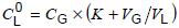
The concentrations in the oil sample are then determined using equation (2), based on Henry's law, which requires that the partition coefficients K and the actual vial volume ratio (VG/VL) for each oil sample be precisely determined.
NOTE VL and VG are calculated according to 7.5.3.2.1 and 7.5.3.4.
A correction for atmospheric pressure and temperature should be made using equation (1) (see 7.5.5.1), replacing "gas-in-oil standard" by gas standard. Generally, gas standards are prepared together with oil samples and so the temperature and pressure inside the vials before head-space extraction should be the same. Concerning the atmospheric pressure, it can vary during the time needed for analysing several samples; as a consequence, in some systems equipped with sample loops in equilibrium with atmospheric pressure, the amount of gas (number of moles) going to the detector through the sample loop can change. Because of this, the correction for atmospheric pressure should be made.
NOTE Although it is not needed for calibration, it is recommended when using this procedure that the overall performance of the extractor be verified regularly by running gas-in-oil standards.
7.5.5.3 Determination of partition coefficients
The preferred method of determination of partition coefficients is by using gas-in-oil standards according to 6.1 or 6.2.
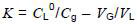
These gas-in-oil standards are analysed under the same conditions as samples from the field. Partition coefficient K for each compound is determined using modified equation (2) (see 7.5.5.2):
where
 is known and Cg is determined by the gas chromatography analysis.
For this determination, Vg and VL should be determined precisely for each vial used (see 7.5.3.2.1).
Alternately, the so-called slope/intercept method can be used: collect 12 30 ml glass syringes of oil where all the gases of interest have been detected. Following 7.5.4.1.2.3, fill 5 sets of 6 vials with the following volumes of oil: 4 ml, 6 ml, 8 ml, 10 ml, 12 ml and 14 ml, corresponding to a phase ratio (VG/VL) of 4,575, 2,716, 1,787, 1,230, 0,86 and 0,59, respectively.
Determine the peak area of each gas under the different phase ratios. Plot the reciprocal of the peak area as the Y-axis and the phase ratio as the X-axis. From the regression analysis of these data, obtain the slope and intercept.
Calculate the partition coefficient of the gas: K = intercept/slope. The highest accuracy on the K value is obtained when the correlation coefficient (R) of the regression is greater than 0,999.
NOTE In the case of the less soluble gases (H2, CO, CO2), precise extrapolation to zero is difficult, so the accuracy of results will be low, but the influence of K in equation (2a) above is also lower for these gases.
Examples of partition coefficients measured experimentally at 70 °C are given in Table 2.
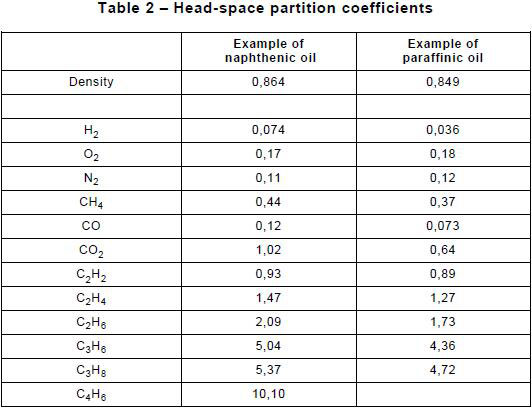
NOTE If the partition coefficients cannot be measured for the oil analysed, approximate values obtained from oils of similar density and chemical composition may be used, such as those indicated in Table 2. For more accurate analyses, the partition coefficients of the oil analysed should be measured.