

IEC 60567 OIL-FILLED ELECTRICAL EQUIPMENT - SAMPLING OF GASES AND OF OIL FOR ANALYSIS OF FREE AND DISSOLVED GASES - GUIDANCE
8 Gas analysis by gas-solid chromatography
8.1 General remarks
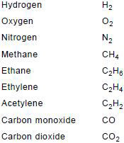
Gas samples, whether obtained from gas-collecting relays or removed from an oil sample, are analysed by gas chromatography. The gases to be determined are:
For the purpose of this guide, C3 hydrocarbons are not required, but they may on occasion give useful information.
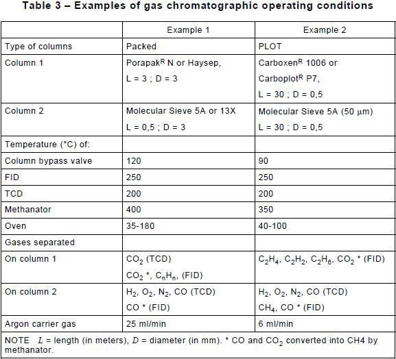
A number of methods may be used for the analyses; the two methods detailed in Table 3 are given as examples that have been found suitable for all extraction techniques.
The following assumes a measure of competence in the techniques of gas chromatography and omits, for brevity, many details which may be found in practical manuals on these techniques.
8.2 Outline of suitable methods using Table 3
In example 1 of Table 3, two separate runs are made, one with a Porapak column (see Note) and the other with a molecular sieve column. A single detector having adequate sensitivity for all the gases to be detected is not available; thus, the gases eluted from the column in use are passed over both a thermal conductivity detector which detects atmospheric gases, CO, CO2 and H2 and a flame ionization detector which detects hydrocarbons.
To determine CO and CO 2 with improved sensitivity a methanator may be fitted at the inlet of the flame ionization detector to convert CO and CO 2 to methane which is then detected by the flame ionization detector.
Porapak is the trade name of products supplied by Water Associates. (Porapaks are porous polymer beads modified to give different retention characteristics. Eight types are available; in order of increasing polarity these are Porapak P, PS, Q, QS, R, S, N, and T).
NOTE This information is given for the convenience of users of this standard and does not constitute an endorsement by the IEC of the products named. Equivalent products may be used if they can be shown to lead to the same results.
In example 2 of Table 3, more sensitive PLOT (porous large open tubular) columns are used, particularly in the case of head-space extraction.
When using a stripping extraction method it may not be possible to achieve the sensitivity and precision for hydrocarbons required for factory tests using less than 5 ml of oil. Larger volumes of oil (10 ml) require longer stripping times to extract the dissolved gases, which would give unacceptable gas chromatograms unless the extracted gases are concentrated by cold trapping.
The method below is written for an apparatus in which the outputs from the detectors are switched electrically so that they may be dealt with by a single channel integrator or single channel chart recorder. Use of a dual channel integrator or recorder eliminates the need for switching.
8.3 Apparatus
8.3.1 Gas chromatograph
Figure 16 is an example of the layout of an instrument which has been used and found acceptable. Injection arrangements shall suit the method by which gas is transferred from gas extraction equipment into the chromatograph.
Thus, the vacuum extraction equipment described in Figure 9 and used for both Toepler pump and partial degassing methods transfers the gas via a gas sample valve and calibrated sample loop, a method recommended to improve repeatability.
Alternatively, gas samples may be transferred and injected into the chromatograph using a precision gas-tight syringe, and this latter method is generally used for gas samples from gas-collecting relays.
In the case of extraction by stripping (see Figure 12), a sampling valve is used, with the stripper inserted in place of the sample loop as shown in Figure 12a. Arrangements where a stripper plus cold trap are used are shown in Figure 12b.
In the case of the head-space method, the head-space accessories described in 7.5.3.1, a bypass valve, and a zero-dead volume adapter (0,53 mm ID) for the column connections are used for injecting extracted gases.
8.3.2 Columns
In the present examples of Table 3, two columns are used with a two-way valve enabling selection between the columns.
However, the important requirement for all columns is that they should achieve good separation in as short a time as possible, while giving all elutions on a stable baseline. The columns indicated in Table 3 are given only by way of examples and other columns meeting these general requirements may be used.
In the case of the head-space method, the packed columns described in example 1 of Table 3 can be used for the routine analysis of oils; however, at low gas-in-oil concentration levels, gases shall be detected in the headspace phase at the ppb level. This requires the use of the PLOT columns of example 2 of Table 3. At these nl/l gas levels, special care should be taken to prevent contamination and in the control of the GC detectors.
8.3.3 Carrier gas
The carrier gas is preferably gas chromatograph grade argon.
8.3.4 Detectors
The gases eluted from the columns are passed over a thermal conductivity detector and a flame ionization detector.
8.3.5 Methanator
In the present examples, a methanator is fitted at the inlet to the flame ionization detector to improve the sensitivity with which CO and CO 2 can be detected by converting these gases to methane.
NOTE The activity of the methanator may be impaired by the presence of sulphur hexafluoride (this gas is sometimes used in cable terminal boxes and may diffuse into the equipment filling oil); in this case, a different analytical arrangement should be used, which is not described in this standard.
8.3.6 Cold trap
When the stripping method is used, a cold trap may be fitted at the outlet of the stripper to improve the sensitivity for hydrocarbons.
Figure 12b shows an example of the method of inclusion of a cold trap. A typical device used consists of a 130 mm long, 6 mm outer diameter, stainless steel tube packed with 100/120 mesh Porapak Q R or equivalent, maintained below -54 °C in a suitable freezing mixture such as solid carbon dioxide and alcohol.
During stripping, a separate carrier gas stream circulates in the cold trap while the main carrier gas flows directly to the gas chromatograph. After stripping, a valve is switched to direct the carrier gas flow through the cold trap. Then the trap is rapidly heated to 80 °C, injecting the trapped gases onto the analytical columns.
8.3.7 Integrator and recorder
The electrical outputs from the detectors are fed to an integrator. Additionally or alternatively, a chart recorder may be used.
8.4 Preparation of apparatus
a) Set up the chromatograph, and allow the flow of carrier gas and the temperature to stabilize as shown by the production of a steady baseline.
b) For the vacuum extraction methods, either inject the gas sample using a syringe or with the gas sample loop previously evacuated.
c) For the stripping method introduce the oil sample into the stripper by means of a precision syringe.
d) For the head-space method inject the extracted gases using accessories indicated in 8.3.1.
8.5 Analysis
See Figure 16.
A possible procedure using one chromatograph fitted with two columns, a gas sampling valve and a methanator is given below (example 1 of Table 3).
a) Adjust the selector valve (4) (position A) to bring the Porapak (5a) or equivalent column into use.
b) Turn the sample valve (2) to introduce the gas sample.
c) Select with switch (10) the flame ionization detector (6b). The first peak to emerge will be CO converted to CH4 by the methanator. The second peak will be CH4. The third peak is CO2 converted to CH4 by the methanator, and this is followed by C2H4, C2H6 and C2H2.
NOTE The CO and CO2 having been converted to CH 4 by the methanator is detected at high sensitivity by the flame ionization detector. At high concentrations, it may well exceed the linear range of this detector. In this circumstance, use may be made of a thermal conductivity detector to evaluate the CO2 before methanation.
d) Adjust the selector valve (4) (position B) to bring the molecular sieve column into use. Obtain a stable baseline.
e) Refill the gas sample loop according to step j) of 7.2.2.
f) Turn the sample valve (2) to introduce the gas sample.
g) Select, with switch (10), the thermal conductivity detector (6a). Peaks will emerge in the order H2, O2 and N2.
h) Select, with switch (10), the flame ionization detector (6b). The next peak will be CH4 ; the last peak to emerge will be CO converted to CH 4 by the methanator.
i) Purge any retained gases from both columns.
j) One determination per gas sample is normally sufficient.
8.6 Calibration of the chromatograph
Retention times are established by injection of dilutions of individual gases in the carrier gas into the columns. The response factors of the detectors, however, are preferably determined using a standard gas mixture diluted with the carrier gas, containing known concentrations of all gas components to be determined, in proportions resembling those found in oils from transformers. Such a standard mixture should be used periodically, depending upon the stability of the equipment. For better precision, calibration should be undertaken immediately before analysis of the oil sample.
The minimum number of standard gas mixtures needed for calibration of the chromatograph varies from 1 to 3. Only one is needed when performance of analysis equipment has been found linear (by verification of the entire system) in the concentration range of gases usually found in transformer oil.
A different standard for verification of GC detectors should be run at least once a day.
8.7 Calculations
a) Identify the gas corresponding to each peak by comparison with the chromatograms obtained during calibration.
b) Measure the area or height of each peak, note its retention time and apply the calibration data to obtain the gas volumes.
c) When dealing with analyses of gases taken from gas collecting relays, calculate the concentration of each gas in per cent by volume.
d) When dealing with analyses of gases extracted from oil, calculate the concentration in microlitres of each gas per litre of the oil from which it was extracted (or micromole of each gas per litre of oil).
Dissolved gas concentrations in the oil sample
 should be converted to these standard conditions (101,325 kPa and 20 °C), using the following equation:
where
is the concentration of gases in oil sample at ambient temperature and pressure;t is the ambient temperature, in °C;
P is the atmospheric pressure, in kPa.
NOTE 1 1 ul/l corresponds to 1 ppm by volume and 0,042 umole/l at 20 °C and 101,3 kPa.
NOTE 2 Concentrations in umoles/l can be converted to ul/l or ppm, under these standard conditions, by multiplying by 22,4 (293/273).
NOTE 3 Total gas content of oil by volume, expressed as a percentage, in the case of partial degassing, stripping and head-space methods, can be estimated by the sum of the individual gas concentrations expressed in ul/l under these standard conditions.