

IEC 60599 Mineral oil-impregnated electrical equipment in service - Guide to the interpretation of dissolved and free gases analysis
6 Conditions for calculating ratios
6.1 Examination of DGA values
DGA sampling and analysis should be done in accordance with the recommendations of IEC 60567.
a) Values of 0 μl/l on a DGA report or below the analytical detection limits S shall be replaced by "below the S value for this gas" (see IEC 60567 for recommended S values)
b) If successive DGA analyses have been performed over a relatively short period of time (days or weeks), inconsistent variations (e.g. brutal decreases of concentrations) may have to be eliminated as an indication of a sampling or analytical problem.
c) Gas ratios are significant and should be calculated only if at least one gas concentration value is above typical value and above typical rate of gas increase (see note 2 of table 2 and clause 9).
d) If gas ratios are different from those for the previous analysis, a new fault may superimpose itself on an old one or normal ageing. In order to get only the gas ratios corresponding to the new fault, subtract the previous DGA values from the last ones and recalculate ratios. This is particularly true in the case of CO and CO2 (see 5.4). Be sure to compare DGA values of samples taken at the same place and preferably in moving oil. Interpretation should also take into account treatments previously made on the equipment, such as repair, oil degassing or filtering, which may affect the level of gases in the oil.
NOTE In the case of air-breathing power transformers, losses occur very slowly with time by diffusion through the conservator or as a result of oil expansion/temperature cycles, with the result that the measured gas levels may be slightly less than the gas levels actually formed in the transformer. However, there is no agreement concerning the magnitude of this diffusion loss in service, some considering it as totally negligible, others as potentially significant, depending on the type of equipment used. In case of doubt, it may be expedient to measure the gas concentration in the conservator to get an idea of the volume ventilated. Significant diffusion losses may affect gas ratios, typical values of gas concentrations and of rates of gas increase.
6.2 Uncertainty on gas ratios
Because of the precision on DGA values, there is also an uncertainty on gas ratios, which can be calculated using the precision on DGA values described in IEC 60567.
Above 10 x S (S being the analytical detection limit), the precision is typically 5 % on DGA values and up to 10 % on a gas ratio. Below 10 x S, the precision on DGA values decreases rapidly, to typically 20 % at 5 x S and up to 40 % on a gas ratio.
Caution should therefore be exercised when calculating gas ratios at low gas levels (lower than 10 x S), keeping in mind the possible variations resulting from the reduced precision. This is particularly true for instrument transformers and bushings, where typical values of gas concentration may be below 10 x S.
7 Application to free gases in gas relays
During a fault, the production rate of gases of all types is closely linked to the rate of energy liberation. Thus, the low rate of energy liberation in partial discharges, or in a low-temperature hot spot, will cause gases to evolve slowly and there is every probability that all the gas produced will dissolve in the oil. The higher rate of energy liberation of a high-temperature core fault, for example, can cause an evolution of gas rapid enough to result in gas bubbles. These will usually partially dissolve in the oil (and exchange with gases already dissolved) but some gas may well reach the gas collecting relay or gas cushion; this gas may approach equilibrium with the gases dissolved in the oil.
A very high rate of energy liberation associated with a power arcing fault causes a rapid and substantial evolution of gas (the resulting pressure surge normally operates the surge element of the gas collecting relay). The large gas bubbles rise quickly to the relay and exchange little gas with the oil so that the gas that collects in the relay is initially far from being in equilibrium with the gases dissolved in the oil. However, if this gas is left for a long time in the relay, some constituents will dissolve, modifying the composition of the gas collected. Acetylene, which is produced in significant quantities by an arcing fault and which is very soluble, is a noteworthy example of a gas which may dissolve comparatively quickly to produce misleading results.
In principle, the analysis of free gases from a gas collecting relay or from a gas cushion may be evaluated in the same way as the analysis of gases dissolved in the oil. However, where the surge element has operated and gas has accumulated in substantial quantities, there is a possibility of having a serious fault, and analyses of the gases should be undertaken to identify the fault. Buchholz alarms due to air accumulation are also possible following a combination of warm days and sudden temperature drops at night.
It is therefore important to collect the gas at the relay as soon as possible without burning it, and sample the oil in the relay and in the main tank.
Where gas has accumulated slowly, assessment of the gases dissolved in the oil is more informative than that of the free gases; this gas-in-oil analysis is also essential in order to determine the total rate of evolution of gases and thus check whether the fault is growing, which is the most important matter to investigate. When analysis of free gases is undertaken, it is necessary to convert the concentrations of the various gases in the free state into equivalent concentrations in the dissolved state, using table 4, before applying the gas ratio method of table 2, and to compare them to the dissolved gas concentrations in the oil of the relay and the main tank.
Applying the principles set out above, comparison of the actual concentrations in the oil with the equivalent concentrations in the free gas may give valuable information on how far gas bubbles may have risen through the oil and, hence, on the rate of gas evolution.
The calculation of dissolved gas concentrations equivalent to free gas concentrations is made by applying the Ostwald coefficient for each gas separately. For a particular gas, the Ostwald coefficient k is defined as follows:
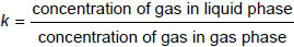
with concentrations in microlitres per litre.
The Ostwald coefficients for various gases in mineral insulating oils at 20 °C and 50 °C are given in table 4.
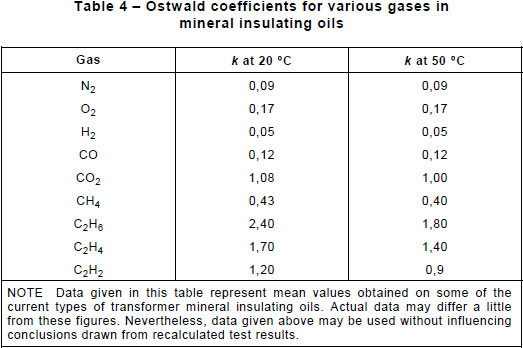
The Ostwald coefficient is independent of the actual partial pressures of the gas concerned. The gas and liquid phases are assumed to be at the same temperature; this is rarely the case but the error introduced by any difference will not invalidate the conclusions reached.