

Section 3. Method B
12 Outline of method
This method determines the gassing characteristics of an insulating liquid and expresses the results in terms of the change in gas volume after a specified test period.
After being dried and saturated with nitrogen gas, the insulating liquid and a nitrogen pocket above the liquid are subjected in the specified cell to a radial electrical stress under the following conditions:
- Voltage: 12 kV;
- Frequency: 50 Hz or 60 Hz;
- Temperature: 80 °C;
- Test duration: 18 h at 50 Hz or 15 h at 60 Hz.
The most significant single feature of the cell is the limited gas volume in contact with the liquid. Because of this factor, gaseous species evolved during the early stages of the gassing test can substantially modify the chemical nature of the gas phase and consequently influence both the rates and the net effect of competitive reactions at the oil-gas interface.
The quantity of gas absorbed or evolved is obtained from the observed changes in gas volume.
13 Apparatus
13.1 Gassing-cell and burette assembly
The gassing-cell shown in Figure 3, page 11, with dimensions as given in Figure 4 and Figure 5, pages 12 and 13, consists of the following components:
13.1.1 Glass cell precision bore (see Figure 4) made of borosilicate glass tubing with a relative permittivity of 5 +/- 0.2 (at 50 Hz and 80 °C) and dimensions as follows:
- tube length: 180 +/- 1 mm;
- tube inside diameter: 16 +/- 0.02 mm;
- tube outside diameter: 20.8 +/- 0.02 mm.
The inner surface is fire-polished, the outside surface ground and machine-polished. The tube is provided with a machine-polished, optically clear plane bottom plate 6 +/- 0.1 mm thick, fused on square with tube axis and made of glass of the same composition as the tube.
A centring cone groove let into the bottom plate has a base of 4 mm and an angle of 90° at the tip of the corner.
The open end of the tube has a small beaded rim.
13.1.2 Outer (high voltage) electrode made of aluminium foil:
- foil thickness: 0.1 mm;
- foil width: 110 mm.
The foil is wound around the tube with its edge terminating flush with the edge of the end plate and fixed by any convenient manner (e.g. by a suitable plastic adhesive tape).
The high voltage supply is connected to the foil by a braided copper lead with a clamp at the end.
13.1.3 Inner (earth) electrode (see Figure 5, page 13) made of free-cutting steel, precision machined and polished to the dimensions shown in Figure 5.
The centring cone protruding from the upper face of the electrode has a base of 4 mm diameter and an angle of 90° at the tip of the cone. The tip is slightly rounded.
All edges are slightly rounded and the electrode surface free from burrs, scratches, or other flaws. The electrode shall be handled with great care and only placed on surfaces covered with filter paper.
O-rings made of suitable resistant material, 11.3 mm inside diameter and 2.4 mm thick should be used to seal the cell.
The electrode is earthed by a braided copper lead with a clamp at the end.
NOTE Free-cutting steel, cold drawn, recommended limits of alloying constituents:
C: max. 0.13 %
Si: max. 0.05 %
P: max. 0.1 %
Mn: 0.6 % to 1.2 %
S: 0.18 % to 0.25 %
13.1.4 Gas-burette, volume 20 cm3, graduated in 0.1 cm3, with an etched scale:
- outside diameter: 13 mm;
- inside diameter: 11 +/- 0.5 mm.
13.1.5 Connecting hose made of suitable resistant flexible material, preferably fluorinated elastomer, for connecting the inner electrode to the gas-burette:
- hose length: 150 mm;
- hose inside diameter: 6 mm;
- wall thickness: 2 mm.
13.1.6 Capillary tubing made of polyethylene, for introducing the test gas (nitrogen) into the glass cell:
- tube length: 750 mm;
- tube inside diameter: 0.4 mm;
- tube outside diameter: 1.1 mm.
13.1.7 Glass syringe, volume 5 cm3.
13.1.8 Holding device (see Figure 6, page 14) preferably made of resin-bonded laminated paper with polyamide screws or of polymethylmethacrylate resin, for holding the test tube:
a) during the filling and assembly of the whole apparatus in the inverse position,
b) during the test, in the normal position, in the oil bath.
The holding device shall be equipped with guides and a resilient mounting for the gassing-cell, with a spring-loaded thrust plate and a retainer to hold it in a correct central position, and with guides and sockets for the high voltage and earth potential leads. The design shall be such as to withstand a voltage of 20 kV between high voltage and earth sockets.
13.2 Heating device
See Sub-clause 4.2.
13.3 Transparent safety shield
See Sub-clause 4.3.
13.4 High voltage transformer
The transformer and its controlling equipment shall be of such size and design that, with a filled gassing-cell in the circuit, the peak factor of the voltage (ratio of peak to r.m.s. voltage) shall not differ by more than +/- 5 % from that of a sinusoidal wave while maintaining 12 kV (r.m.s.) +/- 2 %.
13.5 Thermometer
Any convenient thermometer for measuring a temperature of 80 +/- 0.1 °C (e.g. ISO Standard 653-STL/0.1/60/85).
14 Reagents
14.1 1,1,1-trichloroethane (technical grade).
14.2 n-heptane (analytical grade).
14.3 Nitrogen, oxygen content less than 10 mm 3 /dm 3 and water content less than 2 mm3/dm3, from a cylinder with 2-stage pressure reducer and a fine flow regulator.
15 Preparation of apparatus
General remark:
As the gassing tendency of liquids may be strongly influenced by solvents, it is important that no traces of solvent remain after the cleaning process.
15.1 Dismantle the gassing-cell and burette.
15.2 Clean the test tube, the inner electrode, the gas-burette and the connecting tube by rinsing them inside and outside first with 1,1,1-trichloroethane then with n-heptane.
Normally, the inside of the test tube shall be scrubbed with a stiff polyamide brush to remove waxy deposits from the previous test. Moreover it is useful to polish the surface of the inner electrode carefully from time to time with buffing compound and then with tissue paper moistened with 1,1,1-trichloroethane.
Rinse again first with 1,1,1-trichloroethane, then with n-heptane.
Blow dry with dry compressed air and complete drying in an oven at 80 °C.
15.3 Clean the syringe with n-heptane and then blow dry with dry compressed air.
16 Procedure (see Figure 7, page 15)
16.1 Wrap the high-voltage electrode round the outside of the glass cell and fix it with suitable adhesive tape. The electrode shall embrace the glass cell tightly and its top edge shall terminate level with the top edge of the end plate of the glass cell.
16.2 Insert the glass cell vertically in the holding device with the open end up.
16.3 Fit the connecting hose on to the gas-burette and the inner electrode and secure it with clamping rings. Insert the capillary tube into the burette and push it through until it projects out of the mouth of the oil duct of the inner electrode and extends to the electrode.
16.4 Filter about 50 cm 3 of the oil sample through a previously dried filter paper and rapidly introduce 20 cm 3 of the filtered oil into the glass cell.
16.5 Carefully insert the inner electrode to the end plate of the tube in such a way that the oil slowly rises through the oil duct in the inner electrode and the connecting hose into the burette.
The capillary tube (see Sub-clause 16.3) shall extend to the bottom of the test tube.
Clamp the gas-burette to a tripod so that the entire set-up is in a vertical position with the burette at the top and the cell and electrodes at the bottom. Then pour 5 cm3 of the filtered oil into the burette by means of a syringe.
16.6 Connect the free end of the capillary tube to the nitrogen supply. Before doing this, thoroughly purge the connecting line with nitrogen.
16.7 Saturate the oil with dry nitrogen at a flow rate of 3 dm3/h for 1 h and at room temperature. After that, shut off the nitrogen supply and carefully remove the nitrogen bubbles remaining in the test tube, the oil duct and the connecting hose by repeatedly squeezing the connecting hose.
16.8 Disconnect the burette from the tripod without separating the nitrogen connections.
Clamp the glass cell with the inner electrode to the holding device by means of the retainer and then turn the holding device upside down, keeping the gas-burette vertical. Then clamp the burette to the holding device.
16.9 Record the oil level in the burette.
Inject 3 cm3 of the nitrogen directly from the nitrogen supply through the capillary tube into the test tube recording the volume injected from the indication on the burette.
Then remove the capillary tube.
16.10 Connect the high-voltage socket (on the holding device) to the high-voltage electrode and the earth potential socket (on the holding device) to the shank of the inner electrode by means of braided copper leads and clamp the latter in position.
16.11 Place the test apparatus in the oil bath at room temperature (see note), raise the temperature in about 1 h to the test temperature (80 +/- 0.5 °C).
NOTE Do not place the test apparatus in a hot bath, otherwise the glass might break.
16.12 About 1 h after the test temperature has been reached, i.e. no further change is noticeable in the oil level, record the oil level in the burette (a cm3 , time t0).
Connect the high-voltage and earth potential leads.
Place the safety shield in position and then apply a voltage of 12 kV.
16.13 After 18 h (if 50 Hz) or 15 h (if 60 Hz) record again the burette level (b cm3 , time t1).
16.14 Disconnect the test voltage, switch off the heater and start the circulating cooling system.
16.15 Before taking the test apparatus out of the oil bath, allow to cool to a temperature below 40 °C.
NOTE Do not remove the test apparatus from the hot bath, otherwise the glass might break.
17 Calculation of the results
Calculate the degree of gassing in the presence of nitrogen according to the following formula:
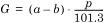
where:
G = gassing tendency, in cubic centimetres
a = burette reading at the beginning of the test (time t0) in cubic centimetres
b = burette reading at the end of the test (time t ), in cubic centimetres
p = barometer reading in kPa
Value G will be positive if gas is evolved and negative if gas is absorbed.
NOTE The stressed volume in the specified cell is about 10 cm 3 . Accordingly, test results can range between -3.0 cm3 and +7.0 cm3
18 Number of tests
Tests should be run in duplicate.
19 Report
The report shall include the following:
- IEC Publication 628-Method B;
- gassing tendency (cm3), mean value of duplicate tests;
- test voltage;
- test voltage frequency (50 Hz or 60 Hz);
- test temperature;
- test period;
- gas phase.
20 Precision
Not yet adequately defined.
However the following figures may be considered indicative for judging the acceptability of results.
Repeatability:
Replicate results by the same operator should not be considered suspect unless they differ by more than 0.5 cm3.
Reproducibility:
The results submitted by each of two laboratories should not be considered suspect unless they differ by more than 1 cm3.